
| Binary Hamming codes | |
|---|---|
The Hamming(7,4) code (with r = 3) |
|
| Named after | Richard W. Hamming |
| Classification | |
| Type | Linear block code |
| Block length | 2r − 1 where r ≥ 2 |
| Message length | 2r − r − 1 |
| Rate | 1 − r/(2r − 1) |
| Distance | 3 |
| Alphabet size | 2 |
| Notation | [2r − 1, 2r − r − 1, 3]2-code |
| Properties | |
| perfect code | |
|
In computer science and telecommunication, Hamming codes are a family of linear error-correcting codes. Hamming codes can detect one-bit and two-bit errors, or correct one-bit errors without detection of uncorrected errors. By contrast, the simple parity code cannot correct errors, and can detect only an odd number of bits in error. Hamming codes are perfect codes, that is, they achieve the highest possible rate for codes with their block length and minimum distance of three.[1]
Richard W. Hamming invented Hamming codes in 1950 as a way of automatically correcting errors introduced by punched card readers. In his original paper, Hamming elaborated his general idea, but specifically focused on the Hamming(7,4) code which adds three parity bits to four bits of data.[2]
In mathematical terms, Hamming codes are a class of binary linear code. For each integer r ≥ 2 there is a code-word with block length n = 2r − 1 and message length k = 2r − r − 1. Hence the rate of Hamming codes is R = k / n = 1 − r / (2r − 1), which is the highest possible for codes with minimum distance of three (i.e., the minimal number of bit changes needed to go from any code word to any other code word is three) and block length 2r − 1. The parity-check matrix of a Hamming code is constructed by listing all columns of length r that are non-zero, which means that the dual code of the Hamming code is the shortened Hadamard code. The parity-check matrix has the property that any two columns are pairwise linearly independent.
Due to the limited redundancy that Hamming codes add to the data, they can only detect and correct errors when the error rate is low. This is the case in computer memory (usually RAM), where bit errors are extremely rare and Hamming codes are widely used, and a RAM with this correction system is a ECC RAM (ECC memory). In this context, an extended Hamming code having one extra parity bit is often used. Extended Hamming codes achieve a Hamming distance of four, which allows the decoder to distinguish between when at most one one-bit error occurs and when any two-bit errors occur. In this sense, extended Hamming codes are single-error correcting and double-error detecting, abbreviated as SECDED.
History[edit]
Richard Hamming, the inventor of Hamming codes, worked at Bell Labs in the late 1940s on the Bell Model V computer, an electromechanical relay-based machine with cycle times in seconds. Input was fed in on punched paper tape, seven-eighths of an inch wide, which had up to six holes per row. During weekdays, when errors in the relays were detected, the machine would stop and flash lights so that the operators could correct the problem. During after-hours periods and on weekends, when there were no operators, the machine simply moved on to the next job.
Hamming worked on weekends, and grew increasingly frustrated with having to restart his programs from scratch due to detected errors. In a taped interview, Hamming said, «And so I said, ‘Damn it, if the machine can detect an error, why can’t it locate the position of the error and correct it?'».[3] Over the next few years, he worked on the problem of error-correction, developing an increasingly powerful array of algorithms. In 1950, he published what is now known as Hamming code, which remains in use today in applications such as ECC memory.
Codes predating Hamming[edit]
A number of simple error-detecting codes were used before Hamming codes, but none were as effective as Hamming codes in the same overhead of space.
Parity[edit]
Parity adds a single bit that indicates whether the number of ones (bit-positions with values of one) in the preceding data was even or odd. If an odd number of bits is changed in transmission, the message will change parity and the error can be detected at this point; however, the bit that changed may have been the parity bit itself. The most common convention is that a parity value of one indicates that there is an odd number of ones in the data, and a parity value of zero indicates that there is an even number of ones. If the number of bits changed is even, the check bit will be valid and the error will not be detected.
Moreover, parity does not indicate which bit contained the error, even when it can detect it. The data must be discarded entirely and re-transmitted from scratch. On a noisy transmission medium, a successful transmission could take a long time or may never occur. However, while the quality of parity checking is poor, since it uses only a single bit, this method results in the least overhead.
Two-out-of-five code[edit]
A two-out-of-five code is an encoding scheme which uses five bits consisting of exactly three 0s and two 1s. This provides ten possible combinations, enough to represent the digits 0–9. This scheme can detect all single bit-errors, all odd numbered bit-errors and some even numbered bit-errors (for example the flipping of both 1-bits). However it still cannot correct any of these errors.
Repetition[edit]
Another code in use at the time repeated every data bit multiple times in order to ensure that it was sent correctly. For instance, if the data bit to be sent is a 1, an n = 3 repetition code will send 111. If the three bits received are not identical, an error occurred during transmission. If the channel is clean enough, most of the time only one bit will change in each triple. Therefore, 001, 010, and 100 each correspond to a 0 bit, while 110, 101, and 011 correspond to a 1 bit, with the greater quantity of digits that are the same (‘0’ or a ‘1’) indicating what the data bit should be. A code with this ability to reconstruct the original message in the presence of errors is known as an error-correcting code. This triple repetition code is a Hamming code with m = 2, since there are two parity bits, and 22 − 2 − 1 = 1 data bit.
Such codes cannot correctly repair all errors, however. In our example, if the channel flips two bits and the receiver gets 001, the system will detect the error, but conclude that the original bit is 0, which is incorrect. If we increase the size of the bit string to four, we can detect all two-bit errors but cannot correct them (the quantity of parity bits is even); at five bits, we can both detect and correct all two-bit errors, but not all three-bit errors.
Moreover, increasing the size of the parity bit string is inefficient, reducing throughput by three times in our original case, and the efficiency drops drastically as we increase the number of times each bit is duplicated in order to detect and correct more errors.
Description[edit]
If more error-correcting bits are included with a message, and if those bits can be arranged such that different incorrect bits produce different error results, then bad bits could be identified. In a seven-bit message, there are seven possible single bit errors, so three error control bits could potentially specify not only that an error occurred but also which bit caused the error.
Hamming studied the existing coding schemes, including two-of-five, and generalized their concepts. To start with, he developed a nomenclature to describe the system, including the number of data bits and error-correction bits in a block. For instance, parity includes a single bit for any data word, so assuming ASCII words with seven bits, Hamming described this as an (8,7) code, with eight bits in total, of which seven are data. The repetition example would be (3,1), following the same logic. The code rate is the second number divided by the first, for our repetition example, 1/3.
Hamming also noticed the problems with flipping two or more bits, and described this as the «distance» (it is now called the Hamming distance, after him). Parity has a distance of 2, so one bit flip can be detected but not corrected, and any two bit flips will be invisible. The (3,1) repetition has a distance of 3, as three bits need to be flipped in the same triple to obtain another code word with no visible errors. It can correct one-bit errors or it can detect — but not correct — two-bit errors. A (4,1) repetition (each bit is repeated four times) has a distance of 4, so flipping three bits can be detected, but not corrected. When three bits flip in the same group there can be situations where attempting to correct will produce the wrong code word. In general, a code with distance k can detect but not correct k − 1 errors.
Hamming was interested in two problems at once: increasing the distance as much as possible, while at the same time increasing the code rate as much as possible. During the 1940s he developed several encoding schemes that were dramatic improvements on existing codes. The key to all of his systems was to have the parity bits overlap, such that they managed to check each other as well as the data.
General algorithm[edit]
The following general algorithm generates a single-error correcting (SEC) code for any number of bits. The main idea is to choose the error-correcting bits such that the index-XOR (the XOR of all the bit positions containing a 1) is 0. We use positions 1, 10, 100, etc. (in binary) as the error-correcting bits, which guarantees it is possible to set the error-correcting bits so that the index-XOR of the whole message is 0. If the receiver receives a string with index-XOR 0, they can conclude there were no corruptions, and otherwise, the index-XOR indicates the index of the corrupted bit.
An algorithm can be deduced from the following description:
- Number the bits starting from 1: bit 1, 2, 3, 4, 5, 6, 7, etc.
- Write the bit numbers in binary: 1, 10, 11, 100, 101, 110, 111, etc.
- All bit positions that are powers of two (have a single 1 bit in the binary form of their position) are parity bits: 1, 2, 4, 8, etc. (1, 10, 100, 1000)
- All other bit positions, with two or more 1 bits in the binary form of their position, are data bits.
- Each data bit is included in a unique set of 2 or more parity bits, as determined by the binary form of its bit position.
- Parity bit 1 covers all bit positions which have the least significant bit set: bit 1 (the parity bit itself), 3, 5, 7, 9, etc.
- Parity bit 2 covers all bit positions which have the second least significant bit set: bits 2-3, 6-7, 10-11, etc.
- Parity bit 4 covers all bit positions which have the third least significant bit set: bits 4–7, 12–15, 20–23, etc.
- Parity bit 8 covers all bit positions which have the fourth least significant bit set: bits 8–15, 24–31, 40–47, etc.
- In general each parity bit covers all bits where the bitwise AND of the parity position and the bit position is non-zero.
If a byte of data to be encoded is 10011010, then the data word (using _ to represent the parity bits) would be __1_001_1010, and the code word is 011100101010.
The choice of the parity, even or odd, is irrelevant but the same choice must be used for both encoding and decoding.
This general rule can be shown visually:
-
Bit position 1 2 3 4 5 6 7 8 9 10 11 12 13 14 15 16 17 18 19 20 … Encoded data bits p1 p2 d1 p4 d2 d3 d4 p8 d5 d6 d7 d8 d9 d10 d11 p16 d12 d13 d14 d15 Parity
bit
coveragep1 
p2 p4
p8 p16

Shown are only 20 encoded bits (5 parity, 15 data) but the pattern continues indefinitely. The key thing about Hamming Codes that can be seen from visual inspection is that any given bit is included in a unique set of parity bits. To check for errors, check all of the parity bits. The pattern of errors, called the error syndrome, identifies the bit in error. If all parity bits are correct, there is no error. Otherwise, the sum of the positions of the erroneous parity bits identifies the erroneous bit. For example, if the parity bits in positions 1, 2 and 8 indicate an error, then bit 1+2+8=11 is in error. If only one parity bit indicates an error, the parity bit itself is in error.
With m parity bits, bits from 1 up to  can be covered. After discounting the parity bits,
  bits remain for use as data. As m varies, we get all the possible Hamming codes:
| Parity bits | Total bits | Data bits | Name | Rate |
|---|---|---|---|---|
| 2 | 3 | 1 | Hamming(3,1) (Triple repetition code) |
1/3 ≈ 0.333 |
| 3 | 7 | 4 | Hamming(7,4) | 4/7 ≈ 0.571 |
| 4 | 15 | 11 | Hamming(15,11) | 11/15 ≈ 0.733 |
| 5 | 31 | 26 | Hamming(31,26) | 26/31 ≈ 0.839 |
| 6 | 63 | 57 | Hamming(63,57) | 57/63 ≈ 0.905 |
| 7 | 127 | 120 | Hamming(127,120) | 120/127 ≈ 0.945 |
| 8 | 255 | 247 | Hamming(255,247) | 247/255 ≈ 0.969 |
| 9 | 511 | 502 | Hamming(511,502) | 502/511 ≈ 0.982 |
| … | ||||
| m | 
|

|
Hamming
|

|
Hamming codes with additional parity (SECDED)[edit]
Hamming codes have a minimum distance of 3, which means that the decoder can detect and correct a single error, but it cannot distinguish a double bit error of some codeword from a single bit error of a different codeword. Thus, some double-bit errors will be incorrectly decoded as if they were single bit errors and therefore go undetected, unless no correction is attempted.
To remedy this shortcoming, Hamming codes can be extended by an extra parity bit. This way, it is possible to increase the minimum distance of the Hamming code to 4, which allows the decoder to distinguish between single bit errors and two-bit errors. Thus the decoder can detect and correct a single error and at the same time detect (but not correct) a double error.
If the decoder does not attempt to correct errors, it can reliably detect triple bit errors. If the decoder does correct errors, some triple errors will be mistaken for single errors and «corrected» to the wrong value. Error correction is therefore a trade-off between certainty (the ability to reliably detect triple bit errors) and resiliency (the ability to keep functioning in the face of single bit errors).
This extended Hamming code was popular in computer memory systems, starting with IBM 7030 Stretch in 1961,[4] where it is known as SECDED (or SEC-DED, abbreviated from single error correction, double error detection).[5] Server computers in 21st century, while typically keeping the SECDED level of protection, no longer use the Hamming’s method, relying instead on the designs with longer codewords (128 to 256 bits of data) and modified balanced parity-check trees.[4] The (72,64) Hamming code is still popular in some hardware designs, including Xilinx FPGA families.[4]
[7,4] Hamming code[edit]

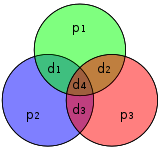
Graphical depiction of the four data bits and three parity bits and which parity bits apply to which data bits
In 1950, Hamming introduced the [7,4] Hamming code. It encodes four data bits into seven bits by adding three parity bits. It can detect and correct single-bit errors. With the addition of an overall parity bit, it can also detect (but not correct) double-bit errors.
Construction of G and H[edit]
The matrix
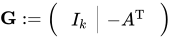 is called a (canonical) generator matrix of a linear (n,k) code,
and 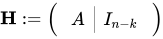 is called a parity-check matrix.
This is the construction of G and H in standard (or systematic) form. Regardless of form, G and H for linear block codes must satisfy
 , an all-zeros matrix.[6]
Since [7, 4, 3] = [n, k, d] = [2m − 1, 2m − 1 − m, 3]. The parity-check matrix H of a Hamming code is constructed by listing all columns of length m that are pair-wise independent.
Thus H is a matrix whose left side is all of the nonzero n-tuples where order of the n-tuples in the columns of matrix does not matter. The right hand side is just the (n − k)-identity matrix.
So G can be obtained from H by taking the transpose of the left hand side of H with the identity k-identity matrix on the left hand side of G.
The code generator matrix  and the parity-check matrix
  are:
are:
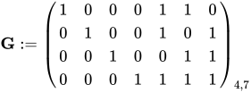
and
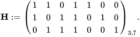
Finally, these matrices can be mutated into equivalent non-systematic codes by the following operations:[6]
- Column permutations (swapping columns)
- Elementary row operations (replacing a row with a linear combination of rows)
Encoding[edit]
- Example
From the above matrix we have 2k = 24 = 16 codewords.
Let  be a row vector of binary data bits,
 ![{displaystyle {vec {a}}=[a_{1},a_{2},a_{3},a_{4}],quad a_{i}in {0,1}}](https://wikimedia.org/api/rest_v1/media/math/render/svg/898ddf319567d4af0acecf5c7fd450f5f466e28b) . The codeword
. The codeword  for any of the 16 possible data vectors is given by the standard matrix product
  where the summing operation is done modulo-2.
For example, let ![{displaystyle {vec {a}}=[1,0,1,1]}](https://wikimedia.org/api/rest_v1/media/math/render/svg/e838e2ec81e9fe6223596b61f747b195d3d338fb) . Using the generator matrix
. Using the generator matrix  from above, we have (after applying modulo 2, to the sum),

[7,4] Hamming code with an additional parity bit[edit]

The same [7,4] example from above with an extra parity bit. This diagram is not meant to correspond to the matrix H for this example.
The [7,4] Hamming code can easily be extended to an [8,4] code by adding an extra parity bit on top of the (7,4) encoded word (see Hamming(7,4)).
This can be summed up with the revised matrices:
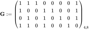
and
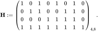
Note that H is not in standard form. To obtain G, elementary row operations can be used to obtain an equivalent matrix to H in systematic form:
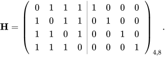
For example, the first row in this matrix is the sum of the second and third rows of H in non-systematic form. Using the systematic construction for Hamming codes from above, the matrix A is apparent and the systematic form of G is written as
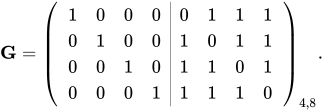
The non-systematic form of G can be row reduced (using elementary row operations) to match this matrix.
The addition of the fourth row effectively computes the sum of all the codeword bits (data and parity) as the fourth parity bit.
For example, 1011 is encoded (using the non-systematic form of G at the start of this section) into 01100110 where blue digits are data; red digits are parity bits from the [7,4] Hamming code; and the green digit is the parity bit added by the [8,4] code.
The green digit makes the parity of the [7,4] codewords even.
Finally, it can be shown that the minimum distance has increased from 3, in the [7,4] code, to 4 in the [8,4] code. Therefore, the code can be defined as [8,4] Hamming code.
To decode the [8,4] Hamming code, first check the parity bit. If the parity bit indicates an error, single error correction (the [7,4] Hamming code) will indicate the error location, with «no error» indicating the parity bit. If the parity bit is correct, then single error correction will indicate the (bitwise) exclusive-or of two error locations. If the locations are equal («no error») then a double bit error either has not occurred, or has cancelled itself out. Otherwise, a double bit error has occurred.
See also[edit]
- Coding theory
- Golay code
- Reed–Muller code
- Reed–Solomon error correction
- Turbo code
- Low-density parity-check code
- Hamming bound
- Hamming distance
Notes[edit]
- ^ See Lemma 12 of
- ^ Hamming (1950), pp. 153–154.
- ^ Thompson, Thomas M. (1983), From Error-Correcting Codes through Sphere Packings to Simple Groups, The Carus Mathematical Monographs (#21), Mathematical Association of America, pp. 16–17, ISBN 0-88385-023-0
- ^ a b c Kythe & Kythe 2017, p. 115.
- ^ Kythe & Kythe 2017, p. 95.
- ^ a b Moon T. Error correction coding: Mathematical Methods and
Algorithms. John Wiley and Sons, 2005.(Cap. 3) ISBN 978-0-471-64800-0
References[edit]
- Hamming, Richard Wesley (1950). «Error detecting and error correcting codes» (PDF). Bell System Technical Journal. 29 (2): 147–160. doi:10.1002/j.1538-7305.1950.tb00463.x. S2CID 61141773. Archived (PDF) from the original on 2022-10-09.
- Moon, Todd K. (2005). Error Correction Coding. New Jersey: John Wiley & Sons. ISBN 978-0-471-64800-0.
- MacKay, David J.C. (September 2003). Information Theory, Inference and Learning Algorithms. Cambridge: Cambridge University Press. ISBN 0-521-64298-1.
- D.K. Bhattacharryya, S. Nandi. «An efficient class of SEC-DED-AUED codes». 1997 International Symposium on Parallel Architectures, Algorithms and Networks (ISPAN ’97). pp. 410–415. doi:10.1109/ISPAN.1997.645128.
- «Mathematical Challenge April 2013 Error-correcting codes» (PDF). swissQuant Group Leadership Team. April 2013. Archived (PDF) from the original on 2017-09-12.
- Kythe, Dave K.; Kythe, Prem K. (28 July 2017). «Extended Hamming Codes». Algebraic and Stochastic Coding Theory. CRC Press. pp. 95–116. ISBN 978-1-351-83245-8.
External links[edit]
- Visual Explanation of Hamming Codes
- CGI script for calculating Hamming distances (from R. Tervo, UNB, Canada)
- Tool for calculating Hamming code
Содержание
- Error Correcting Codes — Hamming codes
- Errors and Error Correcting Codes
- Hamming Code
- Encoding a message by Hamming Code
- Step 1 − Calculation of the number of redundant bits.
- Step 2 − Positioning the redundant bits.
- Step 3 − Calculating the values of each redundant bit.
- Decoding a message in Hamming Code
- Step 1 − Calculation of the number of redundant bits
- Step 2 − Positioning the redundant bits
- Step 3 − Parity checking
- Step 4 − Error detection and correction
- Hamming Code: Error Detection and Correction with Examples
- What is an Error?
- Types of Errors
- Single Bit Errors
- Multiple Bit Errors
- Burst Errors
- What is Error Detection & Error Correction?
- Parity Checking
- Longitudinal Redundancy Check
- Cyclic Redundancy Check
- What is a Hamming code?
- History of Hamming code
- Application of Hamming code
- Advantages of Hamming code
- Disadvantages of Hamming code
- How to Encode a message in Hamming Code
- Decrypting a Message in Hamming code
Error Correcting Codes — Hamming codes
Errors and Error Correcting Codes
When bits are transmitted over the computer network, they are subject to get corrupted due to interference and network problems. The corrupted bits leads to spurious data being received by the receiver and are called errors.
Error-correcting codes (ECC) are a sequence of numbers generated by specific algorithms for detecting and removing errors in data that has been transmitted over noisy channels. Error correcting codes ascertain the exact number of bits that has been corrupted and the location of the corrupted bits, within the limitations in algorithm.
ECCs can be broadly categorized into two types −
Block codes − The message is divided into fixed-sized blocks of bits, to which redundant bits are added for error detection or correction.
Convolutional codes − The message comprises of data streams of arbitrary length and parity symbols are generated by the sliding application of a Boolean function to the data stream.
Hamming Code
Hamming code is a block code that is capable of detecting up to two simultaneous bit errors and correcting single-bit errors. It was developed by R.W. Hamming for error correction.
In this coding method, the source encodes the message by inserting redundant bits within the message. These redundant bits are extra bits that are generated and inserted at specific positions in the message itself to enable error detection and correction. When the destination receives this message, it performs recalculations to detect errors and find the bit position that has error.
Encoding a message by Hamming Code
The procedure used by the sender to encode the message encompasses the following steps −
Step 1 − Calculation of the number of redundant bits.
Step 2 − Positioning the redundant bits.
Step 3 − Calculating the values of each redundant bit.
Once the redundant bits are embedded within the message, this is sent to the user.
Step 1 − Calculation of the number of redundant bits.
If the message contains m𝑚number of data bits, r𝑟number of redundant bits are added to it so that m𝑟 is able to indicate at least (m + r+ 1) different states. Here, (m + r) indicates location of an error in each of (𝑚 + 𝑟) bit positions and one additional state indicates no error. Since, r𝑟 bits can indicate 2 r 𝑟 states, 2 r 𝑟 must be at least equal to (m + r + 1). Thus the following equation should hold 2 r ≥ m+r+1
Step 2 − Positioning the redundant bits.
The r redundant bits placed at bit positions of powers of 2, i.e. 1, 2, 4, 8, 16 etc. They are referred in the rest of this text as r1 (at position 1), r2 (at position 2), r3 (at position 4), r4 (at position  and so on.
Step 3 − Calculating the values of each redundant bit.
The redundant bits are parity bits. A parity bit is an extra bit that makes the number of 1s either even or odd. The two types of parity are −
Even Parity − Here the total number of bits in the message is made even.
Odd Parity − Here the total number of bits in the message is made odd.
Each redundant bit, ri, is calculated as the parity, generally even parity, based upon its bit position. It covers all bit positions whose binary representation includes a 1 in the i th position except the position of ri. Thus −
r1 is the parity bit for all data bits in positions whose binary representation includes a 1 in the least significant position excluding 1 (3, 5, 7, 9, 11 and so on)
r2 is the parity bit for all data bits in positions whose binary representation includes a 1 in the position 2 from right except 2 (3, 6, 7, 10, 11 and so on)
r3 is the parity bit for all data bits in positions whose binary representation includes a 1 in the position 3 from right except 4 (5-7, 12-15, 20-23 and so on)
Decoding a message in Hamming Code
Once the receiver gets an incoming message, it performs recalculations to detect errors and correct them. The steps for recalculation are −
Step 1 − Calculation of the number of redundant bits.
Step 2 − Positioning the redundant bits.
Step 3 − Parity checking.
Step 4 − Error detection and correction
Step 1 − Calculation of the number of redundant bits
Using the same formula as in encoding, the number of redundant bits are ascertained.
2 r ≥ m + r + 1 where m is the number of data bits and r is the number of redundant bits.
Step 2 − Positioning the redundant bits
The r redundant bits placed at bit positions of powers of 2, i.e. 1, 2, 4, 8, 16 etc.
Step 3 − Parity checking
Parity bits are calculated based upon the data bits and the redundant bits using the same rule as during generation of c1,c2 ,c3 ,c4 etc. Thus
c1 = parity(1, 3, 5, 7, 9, 11 and so on)
c2 = parity(2, 3, 6, 7, 10, 11 and so on)
c3 = parity(4-7, 12-15, 20-23 and so on)
Step 4 − Error detection and correction
The decimal equivalent of the parity bits binary values is calculated. If it is 0, there is no error. Otherwise, the decimal value gives the bit position which has error. For example, if c1c2c3c4 = 1001, it implies that the data bit at position 9, decimal equivalent of 1001, has error. The bit is flipped to get the correct message.
Источник
Hamming Code: Error Detection and Correction with Examples
Updated January 7, 2023
What is an Error?
Transmitted data can be corrupted during communication. It is likely to be affected by external noise or other physical failures. In such a situation, the input data can’t be the same as the output data. This mismatch is known as “Error.”
The data errors may result in the loss of important or secure data. Most of the data transfer in digital systems will be in the form of ‘Bit transfer.’ Even a small bit of change can affect the performance of the entire system. In a data sequence, if 1 is changed to 0 or 0 is changed to 1, it is called “Bit error.”
In this Hamming code tutorial, you will learn:
Types of Errors
There are mainly three types of a bit error that occur in data transmission from the sender to the receiver.
- Single bit errors
- Multiple bit errors
- Burst errors

Single Bit Errors
The change made in one bit in the entire data sequence is known as “Single bit error”. However, the occurrence of single-bit error is not that common. Moreover, this error only occurs in a parallel communication system because data is transferred bitwise in a single line. Therefore, there is more chances that a single line can be noisy.
Multiple Bit Errors
In data sequence, if there is a change in two or more bits of a data sequence of a transmitter to receiver, it is known as “Multiple bit errors.”
This type of error mostly occurs in both serial and parallel type data communication networks.
Burst Errors
The change of the set of bits in data sequence is known as “Burst error”. This type of data error is calculated in from the first-bit change to last bit change.
What is Error Detection & Error Correction?
In digital communication system error will be transferred from one communication system into another. If these errors are not detected and corrected, then the data will be lost. For effective communication, system data should transfer with high accuracy. This will be done by first identifying the errors and them correcting them.
Error detection is a method of detecting the errors which are present in the data transmitted from a transmitter to receiver in a data communication system.
Here, you can use redundancy codes to find these errors, by adding to the data when it is transmitted from the source. These codes is called “Error detecting codes”.
Three types of error detection codes are:
- Parity Checking
- Cyclic Redundancy Check (CRC)
- Longitudinal Redundancy Check (LRC)
Parity Checking
- It is also known as a parity check.
- It has a cost-effective mechanism for error detection.
- In this technique, the redundant bit is known as a parity bit. It is appended for every data unit. The total number of 1s in the unit should become even, which is known as a parity bit.
Longitudinal Redundancy Check
In this error detection technique, a block of bits is organized in the tabular format. LRC method helps you to calculate the parity bit for every column. The set of this parity is also sent along with the original data. The block of parity helps you to check the redundancy.
Cyclic Redundancy Check
Cyclic Redundancy Check is a sequence of redundant that must be appended to the end of the unit. That’s why the resulting data unit should become divisible by a second, predetermined binary number.
At the destination, the incoming data needs to be divided by the same number. In case if there is no remainder, then the data unit is assumed to be correct and is accepted. Otherwise, it indicates that the data unit is damaged in transmission, and hence it must be rejected.
What is a Hamming code?
Hamming code is a liner code that is useful for error detection up to two immediate bit errors. It is capable of single-bit errors.
In Hamming code, the source encodes the message by adding redundant bits in the message. These redundant bits are mostly inserted and generated at certain positions in the message to accomplish error detection and correction process.
History of Hamming code
- Hamming code is a technique build by R.W.Hamming to detect errors.
- Hamming code should be applied to data units of any length and uses the relationship between data and redundancy bits.
- He worked on the problem of the error-correction method and developed an increasingly powerful array of algorithms called Hamming code.
- In 1950, he published the Hamming Code, which widely used today in applications like ECC memory.
Application of Hamming code
Here are some common applications of using Hamming code:
- Satellites
- Computer Memory
- Modems
- PlasmaCAM
- Open connectors
- Shielding wire
- Embedded Processor
Advantages of Hamming code
- Hamming code method is effective on networks where the data streams are given for the single-bit errors.
- Hamming code not only provides the detection of a bit error but also helps you to indent bit containing error so that it can be corrected.
- The ease of use of hamming codes makes it best them suitable for use in computer memory and single-error correction.
Disadvantages of Hamming code
- Single-bit error detection and correction code. However, if multiple bits are founded error, then the outcome may result in another bit which should be correct to be changed. This can cause the data to be further errored.
- Hamming code algorithm can solve only single bits issues.
How to Encode a message in Hamming Code
The process used by the sender to encode the message includes the following three steps:
- Calculation of total numbers of redundant bits.
- Checking the position of the redundant bits.
- Lastly, calculating the values of these redundant bits.
When the above redundant bits are embedded within the message, it is sent to the user.
Step 1) Calculation of the total number of redundant bits.
Let assume that the message contains:
- n– number of data bits
- p – number of redundant bits which are added to it so that np can indicate at least (n + p + 1) different states.
Here, (n + p) depicts the location of an error in each of (n + p) bit positions and one extra state indicates no error. As p bits can indicate 2 p states, 2 p has to at least equal to (n + p + 1).
Step 2) Placing the redundant bits in their correct position.
The p redundant bits should be placed at bit positions of powers of 2. For example, 1, 2, 4, 8, 16, etc. They are referred to as p1 (at position 1), p2 (at position 2), p3 (at position 4), etc.
Step 3) Calculation of the values of the redundant bit.
The redundant bits should be parity bits makes the number of 1s either even or odd.
The two types of parity are ?
- Total numbers of bits in the message is made even is called even parity.
- The total number of bits in the message is made odd is called odd parity.
Here, all the redundant bit, p1, is must calculated as the parity. It should cover all the bit positions whose binary representation should include a 1 in the 1st position excluding the position of p1.
P1 is the parity bit for every data bits in positions whose binary representation includes a 1 in the less important position not including 1 Like (3, 5, 7, 9, …. )
P2 is the parity bit for every data bits in positions whose binary representation include 1 in the position 2 from right, not including 2 Like (3, 6, 7, 10, 11,…)
P3 is the parity bit for every bit in positions whose binary representation includes a 1 in the position 3 from right not include 4 Like (5-7, 12-15,… )
Decrypting a Message in Hamming code
Receiver gets incoming messages which require to performs recalculations to find and correct errors.
The recalculation process done in the following steps:
- Counting the number of redundant bits.
- Correctly positioning of all the redundant bits.
- Parity check
Step 1) Counting the number of redundant bits
You can use the same formula for encoding, the number of redundant bits
Here, the number of data bits and p is the number of redundant bits.
Step 2) Correctly positing all the redundant bits
Here, p is a redundant bit which is located at bit positions of powers of 2, For example, 1, 2, 4, 8, etc.
Step 3) Parity check
Parity bits need to calculated based on data bits and the redundant bits.
Источник
Errors and Error Correcting Codes
When bits are transmitted over the computer network, they are subject to get corrupted due to interference and network problems. The corrupted bits leads to spurious data being received by the receiver and are called errors.
Error-correcting codes (ECC) are a sequence of numbers generated by specific algorithms for detecting and removing errors in data that has been transmitted over noisy channels. Error correcting codes ascertain the exact number of bits that has been corrupted and the location of the corrupted bits, within the limitations in algorithm.
ECCs can be broadly categorized into two types −
-
Block codes − The message is divided into fixed-sized blocks of bits, to which redundant bits are added for error detection or correction.
-
Convolutional codes − The message comprises of data streams of arbitrary length and parity symbols are generated by the sliding application of a Boolean function to the data stream.
Hamming Code
Hamming code is a block code that is capable of detecting up to two simultaneous bit errors and correcting single-bit errors. It was developed by R.W. Hamming for error correction.
In this coding method, the source encodes the message by inserting redundant bits within the message. These redundant bits are extra bits that are generated and inserted at specific positions in the message itself to enable error detection and correction. When the destination receives this message, it performs recalculations to detect errors and find the bit position that has error.
Encoding a message by Hamming Code
The procedure used by the sender to encode the message encompasses the following steps −
-
Step 1 − Calculation of the number of redundant bits.
-
Step 2 − Positioning the redundant bits.
-
Step 3 − Calculating the values of each redundant bit.
Once the redundant bits are embedded within the message, this is sent to the user.
Step 1 − Calculation of the number of redundant bits.
If the message contains m𝑚number of data bits, r𝑟number of redundant bits are added to it so that m𝑟 is able to indicate at least (m + r+ 1) different states. Here, (m + r) indicates location of an error in each of (𝑚 + 𝑟) bit positions and one additional state indicates no error. Since, r𝑟 bits can indicate 2r𝑟 states, 2r𝑟 must be at least equal to (m + r + 1). Thus the following equation should hold 2r ≥ m+r+1
Step 2 − Positioning the redundant bits.
The r redundant bits placed at bit positions of powers of 2, i.e. 1, 2, 4, 8, 16 etc. They are referred in the rest of this text as r1 (at position 1), r2 (at position 2), r3 (at position 4), r4 (at position and so on.
Step 3 − Calculating the values of each redundant bit.
The redundant bits are parity bits. A parity bit is an extra bit that makes the number of 1s either even or odd. The two types of parity are −
-
Even Parity − Here the total number of bits in the message is made even.
-
Odd Parity − Here the total number of bits in the message is made odd.
Each redundant bit, ri, is calculated as the parity, generally even parity, based upon its bit position. It covers all bit positions whose binary representation includes a 1 in the ith position except the position of ri. Thus −
-
r1 is the parity bit for all data bits in positions whose binary representation includes a 1 in the least significant position excluding 1 (3, 5, 7, 9, 11 and so on)
-
r2 is the parity bit for all data bits in positions whose binary representation includes a 1 in the position 2 from right except 2 (3, 6, 7, 10, 11 and so on)
-
r3 is the parity bit for all data bits in positions whose binary representation includes a 1 in the position 3 from right except 4 (5-7, 12-15, 20-23 and so on)
Decoding a message in Hamming Code
Once the receiver gets an incoming message, it performs recalculations to detect errors and correct them. The steps for recalculation are −
-
Step 1 − Calculation of the number of redundant bits.
-
Step 2 − Positioning the redundant bits.
-
Step 3 − Parity checking.
-
Step 4 − Error detection and correction
Step 1 − Calculation of the number of redundant bits
Using the same formula as in encoding, the number of redundant bits are ascertained.
2r ≥ m + r + 1 where m is the number of data bits and r is the number of redundant bits.
Step 2 − Positioning the redundant bits
The r redundant bits placed at bit positions of powers of 2, i.e. 1, 2, 4, 8, 16 etc.
Step 3 − Parity checking
Parity bits are calculated based upon the data bits and the redundant bits using the same rule as during generation of c1,c2 ,c3 ,c4 etc. Thus
c1 = parity(1, 3, 5, 7, 9, 11 and so on)
c2 = parity(2, 3, 6, 7, 10, 11 and so on)
c3 = parity(4-7, 12-15, 20-23 and so on)
Step 4 − Error detection and correction
The decimal equivalent of the parity bits binary values is calculated. If it is 0, there is no error. Otherwise, the decimal value gives the bit position which has error. For example, if c1c2c3c4 = 1001, it implies that the data bit at position 9, decimal equivalent of 1001, has error. The bit is flipped to get the correct message.
Introduction
Data storages and transmissions, regardless of the storage and transmission types, are not always error-free. There are always some non-zero probabilities that the data could be changed while it is being stored or transmitted.
For example, DNA is a perfect storage medium for information because DNA is highly stable, much more stable than any of the storage media used in the modern electronics, no matter whether it is the genetic material in vivo or the macromolecule in vitro. However, because of the natural radiations, DNA could always be damaged by radiations with some small probability. Therefore, the information the DNA stored could be altered or lost. In vivo, there are DNA repair mechanisms to fix the errors and damages brought by the radiation, usually based on the intact complementary information stored in the complementary DNA strand. DNA could also be altered while being transmitted, no matter whether it is being replicated by DNA polymerase in vivo or being synthesized from chemicals in vitro. In vivo, there are DNA error-correction mechanisms to fix the incorrect nucleotide being added by the DNA polymerase during DNA synthesis, usually also based on the intact complementary information stored in the complementary DNA strand.
An artificial data storage or transmission system would probably never be as delicate as the in vivo DNA genetic systems. Without some error-correction mechanisms for the artificial data storage and transmission system, the information could be lost forever. Early mathematicians and computer scientists, such as Richard Hamming, invented codes, that could automatically correct the errors introduced during data storage and transmission.
Hamming codes invented by Richard Hamming are a family of linear error-correcting codes and they have been widely used in applications such as error correction code memory (ECC memory). In this article, I would like to try pretending to be Richard Hamming and walk through how Hamming codes were invented mathematically.
Error Detection VS Error Correction
It should be noted that error detection and error correction are different. Usually error detection is much simpler and more efficient whereas error correction could be more complicated and less efficient.
In addition, error detection and error correction does not always work. There are always some small probabilities that error detection and error correction would run into situations that they were not designed to deal with.
Parity
Parity is one of most the simplest error detection codes. It adds a single bit that indicates whether the number of ones (bit-positions with values of one) in the preceding data was even or odd. If an odd number of bits is changed in transmission, the message will change parity and the error can be detected at this point; however, the bit that changed may have been the parity bit itself. The most common convention is that a parity value of one indicates that there is an odd number of ones in the data, and a parity value of zero indicates that there is an even number of ones. If the number of bits changed is even, the check bit will be valid and the error will not be detected.
The following is an example of attaching 1 parity bit to 7 bits of data, making the bit string to always have even number of 1s. Therefore, the XOR of the 8-bit data is always 0.
| Data (7 Bits) | Count of 1-Bits | Parity Bit | Data Including Parity (8 Bits) | XOR |
|---|---|---|---|---|
| 0000000 | 0 | 0 | 00000000 | 0 |
| 1010001 | 3 | 1 | 10100011 | 0 |
| 1101001 | 4 | 0 | 11010010 | 0 |
| 1111111 | 7 | 1 | 11111111 | 0 |
If the bit string has one single error, either in the data or at the parity bit position, the number of 1s in the bit string will not be even, and XOR will not be 0. However, if there are even number of errors in the bit string, the error could never be detected, as XOR would remain 0.
It is obvious that parity could not correct errors when it detects an error because it has no idea where the error happens. Whenever it detects an error, usually the receiver would have to request the sender to transmit the data again, which could be inconvenient and time-consuming.
Repetitions
Repetitions is one of most the simplest error correction codes. It repeats every data bit multiple times in order to ensure that it was sent correctly.
The following is an example of repeating every bit from 3 bits of data 3 times.
| Data (3 Bits) | Number of Repetitions | Data Including Repetitions |
|---|---|---|
| 000 | 3 | 000000000 |
| 010 | 3 | 000111000 |
| 101 | 3 | 111000111 |
| 111 | 3 | 111111111 |
If the bit string has one single error, there would be inconsistency in the 3 bit repetition, and the single inconsistent bit would just be the error. The error could also be fixed by checking the values from the other 2 bits in the repetition. However, if there are two errors in the 3-bit repetition. For example, if the data including three repetitions 000 was incorrectly transmitted as 101, after correction, the data including three repetitions would become 111. The original data was 0, but it was incorrectly corrected to 1 after transmission and error correction.
The incorrect error correction could be mitigated by using larger number of repetitions. The more bit repetitions to vote, the more robust the error correction code to error rate. The drawback is it will reduce the error correction efficiency and is not favorable in a latency demanding data transmission system.
Hamming Codes
In mathematical terms, Hamming codes are a class of binary linear code. For each integer $r geq 2$, where $r$ is the number of error-correction bits, there is a code-word with block length $n = 2^r — 1$ and message length $k = 2^r — r — 1$.
For example, for $r = 3$, the Hamming code has $n = 7$ and $k = 4$. In the 7 bits of the Hamming code, 4 bits are the message we wanted to transmit, the rest 3 bits are error-correction bits which protects the message.
The rate of a block code, defined as the ratio between its message length and its block length, for Hamming codes is therefore
$$
begin{align}
R &= frac{k}{n} \
&= 1 — frac{r}{2^r — 1} \
end{align}
$$
As $r rightarrow infty$, $R rightarrow 1$. When $r$ is very large enough, almost all the bits in the Hamming code are messages.
The Hamming code algorithm would be “created” and derived in the following sections.
Hamming(7,4) Code
Let’s take a look at the core principles of Hamming(7,4) code, that is Hamming code when $r = 3$, first. We will try to come up ways of extending the Hamming(7,4) logic and principles to generic cases.
Hamming(7,4) code consists of 4 data bits, $d_1$, $d_2$, $d_3$, $d_4$, and 3 parity bits, $p_1$, $p_2$, $p_3$. As is shown in the following graphical depiction, the parity bit $p_1$ applies to the data bits $d_1$, $d_2$, and $d_4$, the parity bit $p_2$ applies to the data bits $d_1$, $d_3$, and $d_4$, the parity bit $p_3$ applies to the data bits $d_2$, $d_3$, and $d_4$.
.svg "Graphical Depiction of Hamming(7,4) Code")
When there is no error in the bits, none of the parities will break.
When there is a single error in the data bits, more than one parity will break. For example, say $d_1$ gets an error, the parities where $p_1$ and $p_2$ apply will break and the parity where $p_3$ applies remains. Then we could unambiguously determine $d_1$ gets an error. To correct the error, simply flip the value of $d_1$ as it’s binary.
When there is a single error in the parity bits, only one parity will break. For example, say $p_3$ gets an error, only the parity where $p_3$ applies will break and the parities where $p_1$ and $p_2$ apply remain.
We could see from Hamming(7,4) code that Hamming code is a natural extension from the parity used for error detection.
Create Generic Hamming Code From Scratch
Based on Hamming(7,4) code intuitions and principles, let’s pretend we were the genius Richard Hamming in 1950s and tried to come up with a generic Hamming code for different numbers of error-correction bits.
The number of parity bits $r$, and each parity bit is used only once in one parity. So there are $r$ parities, and the number of different parity states that Hamming code could represent is $2^r$. One parity state has to represent the state that the code has no error. Each of the rest parity states has to represent the state that one unique bit has an error. The number of the rest parity states is $2^r — 1$, therefore, $r$ parity bits could be used for error-correcting codes up to $2^r — 1$ bits. That’s why Hamming code has $r$ number of error-correction bits, the block length $n = 2^r — 1$ and message length $k = 2^r — r — 1$.
The next question is is it possible to and how to arrange $n = 2^r — 1$ bits into $r$ parities so that each single error could be represented by one unique parity state. The graphical depiction of Hamming(7,4) code perfectly tells us how to arrange Hamming code for $r = 3$.
| $d_1$ | $d_2$ | $d_3$ | $d_4$ | $p_1$ | $p_2$ | $p_3$ | |
|---|---|---|---|---|---|---|---|
| $p_1$ | Yes | Yes | No | Yes | Yes | No | No |
| $p_2$ | Yes | No | Yes | Yes | No | Yes | No |
| $p_3$ | No | Yes | Yes | Yes | No | No | Yes |
But what’s the rationale behind this? How to arrange Hamming code for any $r$ that could potentially go very large?
The core principle is that no two bits from the $n = 2^r — 1$ bits will be applied by the same parity bit(s). The following mathematics is the guideline for arranging parity bits.
$$
begin{align}
n &= 2^r — 1 \
&= { {r}choose{0} } + { {r}choose{1} } + { {r}choose{2} } + cdots + { {r}choose{r} } — 1 \
&= { {r}choose{1} } + { {r}choose{2} } + cdots + { {r}choose{r} } \
end{align}
$$
Among the $n = 2^r — 1$ bits, ${r}choose{1}$ bits will be applied by only one parity bit, ${r}choose{2}$ bits will be applied by two parity bits, ${r}choose{3}$ bits will be applied by three parity bits, etc. More specifically, the ${r}choose{1}$ bits have to be the parity bits based on the principle that each parity bit is used only once in one parity.
Theoretically, we could randomly group the $k = n — {r choose 1} = 2^r — r — 1$ bits for the $r choose 2$, $r choose 3$, $cdots$, $r choose r$ groups. As long as the Hamming code decoder knows how the bits were grouped, the decoder could still decode the Hamming code to messages and correct the message based on $r$ parities.
Of course, random grouping does not seem to be optimal. So the next question related to optimization is can we group the bits in a way, rather than random, such that it is more friendly to Hamming code encoding and decoding and we could design efficient Hamming code encoding and decoding algorithms. More formally, given a sequence of $n = 2^r — 1$ bits, how to better assign $n = 2^r — 1$ bit (address) to $r$ parity bits and $k = 2^r — r — 1$ data bits and how to better assign $n = 2^r — 1$ bit (address) to $r$ parity groups?
A more motivating question to ask is, can we make those assignment such that by doing some algebra on the address of parity bits whose parities have been broken we would be able to find out the address of incorrect bits?
Maybe peeking into the Hamming(7,4) code bit assignments could give us some ideas. (I know we are cheating here since we are not really the genius Richard Hamming…)
| $p_1$ | $p_2$ | $d_1$ | $p_3$ | $d_2$ | $d_3$ | $d_4$ | |
|---|---|---|---|---|---|---|---|
| Bit Address | 1 | 2 | 3 | 4 | 5 | 6 | 7 |
| Bit Address (Binary) | 001 | 010 | 011 | 100 | 101 | 110 | 111 |
We noticed that using one-based binary indexing, the addresses of parity bits $p_1$, $p_2$, and $p_3$ are 001, 010, 100, all of which are power of 2. What’s more interesting is, the address of the error bit could be computed from the address of parity bits whose parities have been broken using XOR. Going back to the examples in Hamming(7,4) code, suppose $d_1$ gets an error, the parities where $p_1$ and $p_2$ apply will break. The addresses of $d_1$, $p_1$, and $p_2$, are 011, 001, and 010, respectively. So, $011 = 001 text{XOR} 010$.
Knowing the address assignments of parity bits and data bits, it becomes straightforward to assign the bits to parity groups. To fill the following blanks, we will iterate through all the combinations of $p_1$, $p_2$, and $p_3$, excluding the null combination.
| $p_1$ | $p_2$ | $d_1$ | $p_3$ | $d_2$ | $d_3$ | $d_4$ | |
|---|---|---|---|---|---|---|---|
| Bit Address | 1 | 2 | 3 | 4 | 5 | 6 | 7 |
| Bit Address (Binary) | 001 | 010 | 011 | 100 | 101 | 110 | 111 |
| $p_1$ | |||||||
| $p_2$ | |||||||
| $p_3$ |
All the combinations of $p_1$, $p_2$, and $p_3$, excluding the null combination, are, ($p_1$), ($p_2$), ($p_3$), ($p_1$, $p_2$), ($p_1$, $p_3$), ($p_2$, $p_3$), ($p_1$, $p_2$, $p_3$). The index-XOR (address-XOR) for all the combinations are, 001, 010, 100, 011, 101, 110, 111, respectively. This tells us that bit 001 is guarded by parities where $p_1$ applies, bit 010 is guarded by parities where $p_2$ applies, …, bit 011 is guarded by parities where $p_1$ and $p_2$ applies, …, bit 111 is guarded by parities where $p_1$, $p_2$ and $p_3$ applies.
So the filled table will look like this.
| $p_1$ | $p_2$ | $d_1$ | $p_3$ | $d_2$ | $d_3$ | $d_4$ | |
|---|---|---|---|---|---|---|---|
| Bit Address | 1 | 2 | 3 | 4 | 5 | 6 | 7 |
| Bit Address (Binary) | 001 | 010 | 011 | 100 | 101 | 110 | 111 |
| $p_1$ | Yes | No | Yes | No | Yes | No | Yes |
| $p_2$ | No | Yes | Yes | No | No | Yes | Yes |
| $p_3$ | No | No | No | Yes | Yes | Yes | Yes |
More close examining reveals the following rules for parity bit assignments.
- Parity bit $p_1$ covers all bit address which have the least significant bit set, 001, 011, 101, 111.
- Parity bit $p_2$ covers all bit address which have the second least significant bit set, 010, 011, 110, 111.
- Parity bit $p_3$ covers all bit address which have the third least significant bit set, 100, 101, 110, 111.
Strictly speaking, we would need a mathematical proof for deriving this rule. But we will just skip here.
The address assignment rules for parity bits and data bits and the parity bit assignment rules could be naturally extended to Hamming code for any $r geq 2$.
In addition, knowing exactly the parity group assignment is necessary for Hamming code encoding, but is useless for decoding, as decoding only needs to check the parity bits, compute the address of error bit using the parity bit address, and correct the error bit by flipping if necessary.
Generic Hamming Code Algorithm
Based on our creation of Hamming code from scratch, we could now state the generic Hamming code algorithm. Given a bit string,
- Using one-based binary indexing for all the bits starting from 1, such as 00001, 00010, 00011, etc.
- All bit positions that are powers of two (have a single 1 bit in the binary form of their position) are parity bits, such as 00001, 00010, 00100, 01000, etc.
- All other bit positions, with two or more 1 bits in the binary form of their position, are data bits.
- Each data bit is included in a unique set of 2 or more parity bits, as determined by the binary form of its bit position.
- Parity bit $p_1$ covers all bit address which have the least significant bit set, 00001, 00011, 00101, 00111, etc.
- Parity bit $p_2$ covers all bit address which have the second least significant bit set, 00010, 00011, 00110, 00111, etc.
- Parity bit $p_3$ covers all bit address which have the third least significant bit set, 00100, 00101, 00110, 00111, etc.
- …
- Parity bit $p_i$ covers all bit address which have the i-th least significant bit set.
To encode the message, copy the message on to the data bit positions, and fill the parity bits by computing the parities based on the parity assignments.
To decode the message, check each of the parities. If any parity is broken, get the addresses of parity bits whose parity coverage are broken, and compute the error bit address using XOR for the addresses of broken parity bits that were just found. Once the error bit address was computed, flip the value of the error bit.
Hamming Code Dealing With Multiple Bit Errors
Let’s check one instance of Hamming(7,4) code 0110011 where $p_1 = 0$, $p_2 = 1$, $d_1 = 1$, $p_3 = 0$, $d_2 = 0$, $d_3 = 1$, $d_4 = 1$. Because of two bit errors were introduced, $p_3 = 1$, $d_2 = 1$, the Hamming(7,4) code becomes 0111111, as is shown below.
_example_1011_bits_4_&_5_error.svg "Graphical Depiction of Hamming(7,4) Code with Two Bit Errors")
The parity where $p_1$ applies was broken suggesting that there is an error in the code. However, after fixing the code, the code will become 1111111 which is incorrect.
In general, in addition to Hamming(7,4) code, Hamming code can detect and correct a single error, but it cannot distinguish a double bit error of some codeword from a single bit error of a different codeword. Thus, some double-bit errors will be incorrectly decoded as if they were single bit errors and therefore go undetected, unless no correction is attempted.
Hamming Code With Additional Parity
To remedy the shortcoming of not being able to distinguish single bit error and double bit errors, Hamming codes can be extended by an extra parity bit. In this way, the decoder can detect and correct a single error and at the same time detect (but not correct) a double error.
This extra parity bit creates the parity with all the original Hamming code bits. When single bit error happens, the parity that the extra parity bit applies will break, in addition to the parity breaks from the original Hamming code. When double bit errors happen, the parity that the extra parity bit applies will remain intact, whereas the parity breaks from the original Hamming code remains unchanged.
The following is an example of Hamming(7,4) code with an extra parity bit, making it Hamming(8,4) code.
.svg "Graphical Depiction of Hamming(8,4) Code")
This extended Hamming code is popular in systems such as computer memory, as it will not try to make an correction mistake when double bit errors happen, which is already very rare.
Hamming Code (Binary) Linear Algebra
Hamming code encoding, error detection, error correction, and decoding processes could be represented using (binary) linear algebra.
Consider Hamming(7,4) code, the data bits could be represented using a column vector $mathbf{d} in mathbb{R}^{4}$, where
$$
begin{align}
mathbf{d} &=
begin{bmatrix}
d_1 \
d_2 \
d_3 \
d_4 \
end{bmatrix}
end{align}
$$
Encoding
To encode the data bits $mathbf{d}$, it is actually a (binary) linear transformation using the code generator matrix $mathbf{G}^{4 times 7}$, where
$$
begin{align}
mathbf{G}^{top} &=
begin{bmatrix}
1 & 1 & 0 & 1 \
1 & 0 & 1 & 1 \
1 & 0 & 0 & 0 \
0 & 1 & 1 & 1 \
0 & 1 & 0 & 0 \
0 & 0 & 1 & 0 \
0 & 0 & 0 & 1 \
end{bmatrix}
end{align}
$$
The Hamming(7,4) encoded bits $mathbf{x}$ would be
$$
begin{align}
mathbf{x} &= mathbf{G}^{top} mathbf{d} \
&=
begin{bmatrix}
1 & 1 & 0 & 1 \
1 & 0 & 1 & 1 \
1 & 0 & 0 & 0 \
0 & 1 & 1 & 1 \
0 & 1 & 0 & 0 \
0 & 0 & 1 & 0 \
0 & 0 & 0 & 1 \
end{bmatrix}
begin{bmatrix}
d_1 \
d_2 \
d_3 \
d_4 \
end{bmatrix} \
&=
begin{bmatrix}
d_1 + d_2 + d_4 \
d_1 + d_3 + d_4 \
d_1 \
d_2 + d_3 + d_4 \
d_2 \
d_3 \
d_4 \
end{bmatrix} \
&=
begin{bmatrix}
d_1 + d_2 + d_4 \
d_1 + d_3 + d_4 \
d_1 \
d_2 + d_3 + d_4 \
d_2 \
d_3 \
d_4 \
end{bmatrix}
mod 2 \
&=
begin{bmatrix}
(d_1 + d_2 + d_4) mod 2 \
(d_1 + d_3 + d_4) mod 2 \
d_1 \
(d_2 + d_3 + d_4) mod 2 \
d_2 \
d_3 \
d_4 \
end{bmatrix} \
&=
begin{bmatrix}
p_1 \
p_2 \
d_1 \
p_3 \
d_2 \
d_3 \
d_4 \
end{bmatrix} \
end{align}
$$
The modulo is to compute the parity bits for even parity.
Also notice that the code generator matrix $mathbf{G}$ could be easily derived from the bit sequence and parity table.
Error Detection
Suppose the actual Hamming(7,4) encoded bits received is $mathbf{x}^{prime}$, and $mathbf{x}^{prime}$ may or may not equal to $mathbf{x}$.
The error detection is just parity checking by applying the parity checking matrix $mathbf{H} in mathbb{R}^{3 times 7}$ on $mathbf{x}^{prime}$, where
$$
begin{align}
mathbf{H} &=
begin{bmatrix}
1 & 0 & 1 & 0 & 1 & 0 & 1 \
0 & 1 & 1 & 0 & 0 & 1 & 1 \
0 & 0 & 0 & 1 & 1 & 1 & 1 \
end{bmatrix}
end{align}
$$
$$
begin{align}
mathbf{z} = mathbf{H} mathbf{x}^{prime}
end{align}
$$
If $mathbf{x} = mathbf{x}^{prime}$, we must have $mathbf{z} = mathbf{0}$.
$$
begin{align}
mathbf{z} &= mathbf{H} mathbf{x}^{prime} \
&= mathbf{H} mathbf{x} \
&=
begin{bmatrix}
1 & 0 & 1 & 0 & 1 & 0 & 1 \
0 & 1 & 1 & 0 & 0 & 1 & 1 \
0 & 0 & 0 & 1 & 1 & 1 & 1 \
end{bmatrix}
begin{bmatrix}
p_1 \
p_2 \
d_1 \
p_3 \
d_2 \
d_3 \
d_4 \
end{bmatrix} \
&=
begin{bmatrix}
p_1 + d_1 + d_2 + d_3 \
p_2 + d_1 + d_3 + d_4 \
p_3 + d_d + d_3 + d_4 \
end{bmatrix} \
&=
begin{bmatrix}
p_1 + d_1 + d_2 + d_3 \
p_2 + d_1 + d_3 + d_4 \
p_3 + d_d + d_3 + d_4 \
end{bmatrix} mod 2 \
&=
begin{bmatrix}
0 \
0 \
0 \
end{bmatrix} \
&= mathbf{0} \
end{align}
$$
Also notice that the parity checking matrix $mathbf{H}$ is just the bit sequence and parity table.
A more interesting property of $mathbf{H}$ is that each column in $mathbf{H}$ is actually binary index sequence, 1, 2, 3, etc.
$$
begin{align}
mathbf{H} &=
begin{bmatrix}
1 & 0 & 1 & 0 & 1 & 0 & 1 \
0 & 1 & 1 & 0 & 0 & 1 & 1 \
0 & 0 & 0 & 1 & 1 & 1 & 1 \
end{bmatrix} \
&=
begin{bmatrix}
1 & 2 & 3 & 4 & 5 & 6 & 7 \
end{bmatrix}_{10}
end{align}
$$
This property will be very useful for error correction.
Error Correction
Suppose there is a single bit error at bit position $i$ (one-based), the actual Hamming encoded code received would be
$$
mathbf{x}^{prime} = mathbf{x} + mathbf{e}_{i}
$$
Parity checking would just yield the bit error position in binary.
$$
begin{align}
mathbf{z} &= mathbf{H} mathbf{x}^{prime} \
&= mathbf{H} left( mathbf{x} + mathbf{e}_{i} right) \
&= mathbf{H} mathbf{x} + mathbf{H} mathbf{e}_{i} \
&= mathbf{0} + mathbf{H} mathbf{e}_{i} \
&= mathbf{H} mathbf{e}_{i} \
&=
begin{bmatrix}
1 & 2 & 3 & 4 & 5 & 6 & 7 \
end{bmatrix}_{10}
mathbf{e}_{i} \
&= i \
&= (i)_{2} \
end{align}
$$
The resulting value would be non-zero if there is a bit error.
To fix the bit error, simply flip the bit value at address $mathbf{z}$.
Decoding
Decoding is simple. Suppose the corrected Hamming code is $mathbf{d}_{r}$, and the decoding matrix $mathbf{R} in mathbb{R}^{4 times 7}$, where
$$
begin{align}
mathbf{R} &=
begin{bmatrix}
0 & 0 & 1 & 0 & 0 & 0 & 0 \
0 & 0 & 0 & 0 & 1 & 0 & 0 \
0 & 0 & 0 & 0 & 0 & 1 & 0 \
0 & 0 & 0 & 0 & 0 & 0 & 1 \
end{bmatrix}
end{align}
$$
Also notice that the code generator matrix $mathbf{R}$ could be easily derived from the bit sequence and parity table.
Perfect Code
Minimum Distance
The distance or minimum (Hamming) distance $d$ of a block code is the minimum number of positions in which any two distinct codewords differ.
Because each message bit is covered by at least two parities, changing one message bit will result in changing at least three bits in codeword. Changing two message bits will result in changing at least three bits in codeword as well. So the distance of Hamming code $d = 3$.
In fact, a code with distance $d$ allows the receiver to detect up to $d-1$ transmission errors since changing $d-1$ positions of a codeword can never accidentally yield another codeword. Furthermore, if no more than $(d-1)/2$ transmission errors occur, the receiver can uniquely decode the received word to a codeword. This is because every received word has at most one codeword at distance $(d-1)/2$. If more than $(d-1)/2$ transmission errors occur, the receiver cannot uniquely decode the received word in general as there might be several possible codewords.
To understand this more intuitively, suppose we have certain number of people standing on a playground, the distance can only be integer, and the minimum distance between any two people is $d$. Given a circle of a radius of $(d-1)/2$ around each people, we know the closest person to all the points in the circle is the person in the center of the circle. If the radius of circles becomes $d — 1$, there are some chances that the closest person to all the points in the circle is not the person in the center of the circle, but the choices of the closest person is very limited. If the radius of circles becomes even larger, it is almost impossible to have the closest person to be the one in the center of the circle.
Hamming Bound
With the understanding of minimum distance from Hamming code, we could further derive Hamming bound, an important limitation on the efficiency with which any error-correcting code can utilize the space in which its code words are embedded. A code that attains the Hamming bound is said to be a perfect code.
An alphabet set $mathcal{A}_{q}$ is a set of symbols with $q$ elements and $lvert mathcal{A}_{q} rvert = q$. The set of strings of length $n$ on the alphabet set $mathcal{A}_{q}$ are denoted $mathcal{A}_{q}^{n}$ and $lvert mathcal{A}_{q}^{n} rvert = q^n$. A $q$-ary block code of length $n$ is a subset of the strings of $mathcal{A}_{q}^{n}$.
Let $A_{q}(n,d)$ denote the maximum possible size of a $q$-ary block code $C$ of length $n$ and minimum Hamming distance $d$ between elements of the block code (necessarily positive for $q^{n}>1$).
Then, the Hamming bound is:
$$
A_{q}(n,d) leq frac{q^n}{sum_{k=0}^{t} {n choose k} (q-1)^k }
$$
where
$$
t = leftlfloor frac{d-1}{2} rightrfloor
$$
Proof
Similar to what we have discussed in the minimum distance section, for each codeword $c$ in $q$-ary block code $C$, consider a ball of fixed radius of $t$ around $c$, where $t$ is just the minimum distance. The number of words $m$ that could deviate at most $t$ components from the center of the sphere, which is a codeword, could be computed using combinations.
$$
m = sum_{k=0}^{t} {n choose k} (q-1)^k
$$
Because $A_{q}(n,d)$ is the maximum number of codewords in $C$, we must have
$$
A_{q}(n,d) times m leq lvert mathcal{A}_{q}^{n} rvert
$$
Therefore,
$$
A_{q}(n,d) leq frac{q^n}{sum_{k=0}^{t} {n choose k} (q-1)^k }
$$
This concludes the proof. $square$
Hamming Codes
A code that attains the Hamming bound is said to be a perfect code. Perfect code achieves the highest possible rate for codes with their block length and minimum distance.
Hamming codes are perfect codes. Let’s verify it.
Proof
For Hamming codes, as we have derived previously, $q$ = 2 because Hamming codes are binary codes, code length $n = 2^r — 1$, message length $k = 2^r — r — 1$, and minimum distance $t = lfloor (d — 1) / 2 rfloor = 1$.
$$
begin{align}
A_{q}(n,d) &= q^{k} \
&= 2^{2^r — r — 1} \
end{align}
$$
$$
begin{align}
frac{q^n}{sum_{i=0}^{t} {n choose i} (q-1)^i }
&= frac{2^n}{sum_{i=0}^{1} {n choose i} 1^i } \
&= frac{2^n}{ {n choose 0} + {n choose 1} } \
&= frac{2^n}{ 1 + n } \
&= frac{2^{2^r — 1}}{ 1 + 2^r — 1 } \
&= frac{2^{2^r — 1}}{ 2^r } \
&= 2^{2^r — r — 1} \
end{align}
$$
Therefore, for Hamming codes,
$$
A_{q}(n,d) = frac{q^n}{sum_{k=0}^{t} {n choose k} (q-1)^k }
$$
Hamming code is perfect code.
This concludes the proof. $square$
As I mentioned, random parity grouping would also work in Hamming code for error correction but it would just be less efficient. The way Richard Hamming was assigning the bits to parity groups was the only part that we “cheated” in this article. There must be some mathematical motivations behind this, which I did not get time to research and explore.
That’s why Richard Hamming was a famous mathematician but I am not 
References
- Hamming Code
- Hamming Distance
- Hamming Bound
Improve Article
Save Article
Improve Article
Save Article
Hamming code is a set of error-correction codes that can be used to detect and correct the errors that can occur when the data is moved or stored from the sender to the receiver. It is a technique developed by R.W. Hamming for error correction. Redundant bits – Redundant bits are extra binary bits that are generated and added to the information-carrying bits of data transfer to ensure that no bits were lost during the data transfer. The number of redundant bits can be calculated using the following formula:
 2^r ≥ m + r + 1
 where, r = redundant bit, m = data bit
Suppose the number of data bits is 7, then the number of redundant bits can be calculated using: = 2^4 ≥ 7 + 4 + 1 Thus, the number of redundant bits= 4 Parity bits. A parity bit is a bit appended to a data of binary bits to ensure that the total number of 1’s in the data is even or odd. Parity bits are used for error detection. There are two types of parity bits:
- Even parity bit: In the case of even parity, for a given set of bits, the number of 1’s are counted. If that count is odd, the parity bit value is set to 1, making the total count of occurrences of 1’s an even number. If the total number of 1’s in a given set of bits is already even, the parity bit’s value is 0.
- Odd Parity bit – In the case of odd parity, for a given set of bits, the number of 1’s are counted. If that count is even, the parity bit value is set to 1, making the total count of occurrences of 1’s an odd number. If the total number of 1’s in a given set of bits is already odd, the parity bit’s value is 0.
General Algorithm of Hamming code: Hamming Code is simply the use of extra parity bits to allow the identification of an error.
- Write the bit positions starting from 1 in binary form (1, 10, 11, 100, etc).
- All the bit positions that are a power of 2 are marked as parity bits (1, 2, 4, 8, etc).
- All the other bit positions are marked as data bits.
- Each data bit is included in a unique set of parity bits, as determined its bit position in binary form. a. Parity bit 1 covers all the bits positions whose binary representation includes a 1 in the least significant position (1, 3, 5, 7, 9, 11, etc). b. Parity bit 2 covers all the bits positions whose binary representation includes a 1 in the second position from the least significant bit (2, 3, 6, 7, 10, 11, etc). c. Parity bit 4 covers all the bits positions whose binary representation includes a 1 in the third position from the least significant bit (4–7, 12–15, 20–23, etc). d. Parity bit 8 covers all the bits positions whose binary representation includes a 1 in the fourth position from the least significant bit bits (8–15, 24–31, 40–47, etc). e. In general, each parity bit covers all bits where the bitwise AND of the parity position and the bit position is non-zero.
- Since we check for even parity set a parity bit to 1 if the total number of ones in the positions it checks is odd.
- Set a parity bit to 0 if the total number of ones in the positions it checks is even.
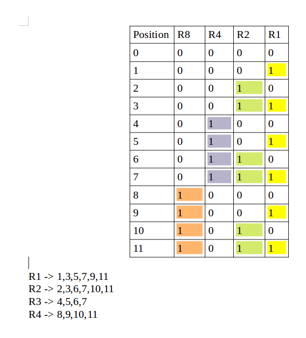
Determining the position of redundant bits – These redundancy bits are placed at positions that correspond to the power of 2.
As in the above example:
- The number of data bits = 7
- The number of redundant bits = 4
- The total number of bits = 11
- The redundant bits are placed at positions corresponding to power of 2- 1, 2, 4, and 8
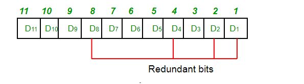
- Suppose the data to be transmitted is 1011001, the bits will be placed as follows:
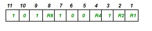
Determining the Parity bits:
- R1 bit is calculated using parity check at all the bits positions whose binary representation includes a 1 in the least significant position. R1: bits 1, 3, 5, 7, 9, 11
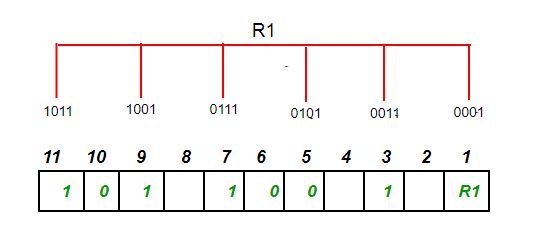
- To find the redundant bit R1, we check for even parity. Since the total number of 1’s in all the bit positions corresponding to R1 is an even number the value of R1 (parity bit’s value) = 0
- R2 bit is calculated using parity check at all the bits positions whose binary representation includes a 1 in the second position from the least significant bit. R2: bits 2,3,6,7,10,11
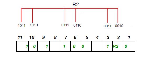
- To find the redundant bit R2, we check for even parity. Since the total number of 1’s in all the bit positions corresponding to R2 is odd the value of R2(parity bit’s value)=1
- R4 bit is calculated using parity check at all the bits positions whose binary representation includes a 1 in the third position from the least significant bit. R4: bits 4, 5, 6, 7
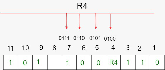
- To find the redundant bit R4, we check for even parity. Since the total number of 1’s in all the bit positions corresponding to R4 is odd the value of R4(parity bit’s value) = 1
- R8 bit is calculated using parity check at all the bits positions whose binary representation includes a 1 in the fourth position from the least significant bit. R8: bit 8,9,10,11

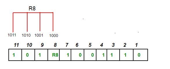
- To find the redundant bit R8, we check for even parity. Since the total number of 1’s in all the bit positions corresponding to R8 is an even number the value of R8(parity bit’s value)=0. Thus, the data transferred is:

Error detection and correction: Suppose in the above example the 6th bit is changed from 0 to 1 during data transmission, then it gives new parity values in the binary number:
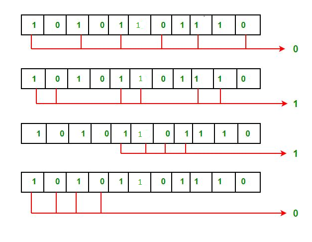
The bits give the binary number 0110 whose decimal representation is 6. Thus, bit 6 contains an error. To correct the error the 6th bit is changed from 1 to 0.