- Code: 0030
- Description: FAX PWB system error The FAX process cannot be continued due to the malfunction of the FAX PWB.
- Remedy: FAX PWB 1. Unplug the power cord from the wall outlet, and wait five seconds. Then plug in the power cord and then turn on the power switch. 2. Reinstall the FAX firmware. 3. Replace the FAX PWB.
- Code: 0070
- Description: FAX PWB incompatible detection error In the initial communication with the FAX PWB, any normal communication command is not transmitted.
- Remedy: Main/engine PWB Replace the main/engine PWB.
- Code: 0100
- Description: Backup memory device error Outputs an abnormal status from the flash memory.
- Remedy: Flash memory (Main/Engine PWB) 1. Unplug the power cord from the wall outlet, and wait five seconds. Then plug in the power cord and then turn on the power switch. 2. Check that the connectors on the main/engine PWB are properly connected, and if not, re-connect them. 3. Replace the main/engine PWB.
- Code: 0120
- Description: MAC address data error In case MAC address is invalid data
- Remedy: Flash memory (Main/Engine PWB) 1. Unplug the power cord from the wall outlet, and wait five seconds. Then plug in the power cord and then turn on the power switch. 2. Check the MAC address on the network status page. 3. If it is blank, obtain an EEPROM with its MAC address written by the service support and install it. 4. Replace the main/engine PWB.
- Code: 0130
- Description: Backup memory Read/write error (Main/ Engine PWB) Read/write to the NAND memory cannot be executed.
- Remedy: Flash memory (Main/Engine PWB) 1. Unplug the power cord from the wall outlet, and wait five seconds. Then plug in the power cord and then turn on the power switch. 2. Check that the connectors on the main/engine PWB are properly connected, and if not, re-connect them. 3. Replace the main/engine PWB.
- Code: 0140
- Description: Backup memory data error (Main/Engine PWB) At power up, the data that was read from the NAND memory has been determined to be a error.
- Remedy: Flash memory (Main/Engine PWB) 1. Unplug the power cord from the wall outlet, and wait five seconds. Then plug in the power cord and then turn on the power switch. 2. Execute U021 initialize memory. 3. Replace the main/engine PWB.
- Code: 0150
- Description: EEPROM read/ write error (Main/Engine PWB) No response is issued from the device in reading/ writing for 5 ms or more and this problem is repeated 5 times successively. Mismatch of reading data from two locations occurs 8 times successively. Mismatch between writing data and reading data occurs 8 times successively.
- Remedy: EEPROM (Main/Engine PWB) 1. Unplug the power cord from the wall outlet, and wait five seconds. Then plug in the power cord and then turn on the power switch. 2. Check that the EEPROM is properly installed on the main/ engine PWB and if not, reinstall it. 3. Replace the main/engine PWB. 4. Check the EEPROM and if it is damaged, contact the service support.
- Code: 0160
- Description: EEPROM data error (Main/Engine PWB) Reading data from EEPROM is detected abnormal.
- Remedy: EEPROM (Main/Engine PWB) 1. Unplug the power cord from the wall outlet, and wait five seconds. Then plug in the power cord and then turn on the power switch. 2. Execute U021 initialize memory. 3. If the EEPROM data is corrupted, contact the service support.
- Code: 0170
- Description: Billing counting error Mismatch between the value of the main/engine PWB and EEPROM, in one of the value of billing counter, life counter, or scanner counter.
- Remedy: EEPROM (Main/Engine PWB) 1. Check that the EEPROM installed in the main/ engine PWB is correct and, if not, install the correct EEPROM for the model. 2. Replace the main/engine PWB. 3. If the EEPROM data is corrupted, contact the service support.
- Code: 0180
- Description: Machine number mismatch When the power is turned on, the machine number does not match the one stored in the main/engine PWB.
- Remedy: EEPROM (Main/Engine PWB) 1. Check that the EEPROM installed in the main/ engine PWB is correct and, if not, install the correct EEPROM for the model. 2. Confirm the serial number data for the main/ engine PWB by using U004. If the mutually different machine number data between «Machine No. (Main)» and «Machine No. (Eng)» is displayed, or if there is a difference between the actual machine number and the number of «Machine No. (Eng)», install the correct EEPROM, and then execute U004.
- Code: 0190
- Description: Backup memory device error (engine) Unable to read out data from the IC on the main unit PWB. Read out data from the IC on the main unit PWB. (3 retrials)
- Remedy: EEPROM (Main/Engine PWB) 1. Unplug the power cord from the wall outlet, and wait five seconds. Then plug in the power cord and then turn on the power switch. 2. Check that the connectors on the main/engine PWB are properly connected, and if not, re-connect them. 3. Contact service headquarters to get an EEPROM to install.
- Code: 0800
- Description: Image formation problems The printing sequence JAM (J010X) is detected for 2 consecutive times.
- Remedy: Main/Engine PWB 1. Check if the problem is a printing operation error detection in a particular file, and if it is possible to obtain the reproduction of the phenomena by the identification of the job that detected the error, and take the job log. 2. If the problem occurs in an unspecified job, check the connectors on the main/engine PWB, and reattach it. 3. Replace the main/engine PWB.
- Code: 0830
- Description: FAX PWB flash Program area Checksum error The program stored in the flash memory on the FAX PWB is broken and cannot be executed.
- Remedy: FAX firmware Reinstall the FAX firmware.
FAX PWB 1. Unplug the power cord from the wall outlet, and reinstall the FAX PWB, and then plug in the power cord and turn the power on. 2. Check the connection failure between the KUIO connector of the main/engine PWB and FAX PWB, and reconnect it. 3. Execute [Initializing] by U600. 4. Replace the FAX PWB.
- Code: 0840
- Description: Faults of RTC [Check at powerup] The RTC setting has reverted to a previous state. Or, the machine has not been turned on for 5 years (regularly compared with a set value stored in the EEPROM). The RTC setting is older than 00:01 on January 1, 2000. [Checked periodically (at every 5 minutes) after powerup.] The RTC setting has reverted to a state older than the last time it was checked. 10 minutes have been passed since the previous check.
- Remedy: Settings of RTC Execute Date Setting using the system menu.
Backup battery (Main/Engine PWB) 1. Check if the backup battery on the main/engine PWB is not short-circuited. 2. Unplug the power cord from the wall outlet, and wait five seconds. Then plug in the power cord and then turn on the power switch. Then plug in the power cord and then turn on the power switch. If the same service call error is displayed, replace the backup battery.
Main/Engine PWB 1. If the communication error (due to a noise, etc.) is present with the RTC on the main/engine PWB, check that the PWB is properly grounded or secured by screws. 2. Replace the main/engine PWB.
- Code: 0870
- Description: FAX PWB — Main/Engine PWB image data transfer error High-capacity data transfer between the FAX PWB and the main/engine PWB was not normally performed even if the data transfer was retried the specified times.
- Remedy: FAX PWB 1. Unplug the power cord from the wall outlet, and wait five seconds. Reinstall the FAX PWB, and then plug in the power cord and turn the power on. 2. Check the connection failure between the KUIO connector of the main/engine PWB and FAX PWB, and reconnect it. 3. Replace the FAX PWB.
Main/Engine PWB Replace the main/engine PWB.
- Code: 0920
- Description: Fax file system error The backup data is not retained for file system abnormality of the flash memory of the FAX PWB.
- Remedy: FAX PWB 1. Execute [Initializing] by U600.Reinstall the FAX firmware. 2. Unplug the power cord from the wall outlet, and wait five seconds. Reinstall the FAX PWB, and then plug in the power cord and turn the power on. 3. Check the connection failure between the KUIO connector of the main/engine PWB and FAX PWB, and reconnect it. 4. Replace the FAX PWB.
- Code: 0970
- Description: 24V power down detect
- Remedy: Low voltage power supply PWB 1. Check that the interlock switch (ILSW) is turned on properly by the rear cover closing. 2. Check if there is a defective connection in the connector of the low voltage power supply PWB, and then check the 24V output from the main/ engine PWB (YC1-7, 8). 3. Replace the low voltage power supply PWB.
Main/Engine PWB 1. Unplug the power cord from the wall outlet, and wait five seconds. Then plug in the power cord and then turn on the power switch. 2. Check that the connectors on the main/engine PWB are properly connected, and if not, re-connect them. 3. Replace the main/engine PWB.
- Code: 1810
- Description: Paper feeder Communication error No PF connection is detected after PF connection is detected at powerup PF detection.
- Remedy: Paper feeder Check the wiring connection status with the main unit, and if necessary, reconnect it.
PF main PWB 1. Confirm that the wiring connector is firmly connected, and if necessary, connect the connector all the way in. DP main PWB — Main/Engine PWB (YC47) 2. If the wiring is disconnected, short-circuited or has a ground fault, replace the wire. 3. Replace the PF PWB.
Main/Engine PWB 1. Check the engine firmware and upgrade to the latest version if necessary. 2. Replace the main/engine PWB.
- Code: 2200
- Description: Main motor steady-state error After the motor is stabilized, the ready signal is turned OFF for continuous 1 s.
- Remedy: Drum unit BK Check that the drum can be rotated by hand, and if it is locked, replace the drum unit BK.
Defective connector cable or poor contact in the connector 1. Reconnect the connector if its connection is loose. 2. Check the continuity within the connector wire. If none, replace the wire. Main motor — Main/Engine PWB (YC11)
Main motor drive transmission system 1. Check if the couplings and gears rotate smoothly, and if not, clean or grease the gears. 2. Check for broken couplings and gears, and replace if any are found.
Main motor Replace the main motor.
Main/Engine PWB Replace the main/engine PWB.
- Code: 2500
- Description: Paper feed motor error After the motor starting, the ready signal is not turned ON for continuous 2 s. In case the Ready signal does not turn ON 1s in succession after the motor is in the steady-state.
- Remedy: Defective connector cable or poor contact in the connector 1. Reconnect the connector if its connection is loose. 2. Check the continuity within the connector wire. If none, replace the wire. Paper feed motor — container relay PWB (YC11)
Drive transmission system for the paper feed motor 1. Check if the rollers and gears rotate smoothly. If not, clean or grease the bushes and gears. 2. Check for broken gears and replace if any are found.
Paper feed motor Replace the paper feed motor.
Main/Engine PWB Replace the main/engine PWB.
- Code: 3100
- Description: Carriage error When turning the power on, or when the reading of the original document by table or DP scanning has completed, the home position sensor is not turned off, even if the home position sensor is on and the scanner carriage moves to the scanning direction. ?Or, the home position sensor does not turn on, even if the home position sensor is off and the scanner carriage moves to the return direction.
- Remedy: Scanner motor 1. Move the scanner by hand to check whether it smoothly moves. 2. Check that the scanner drive belt is not disengaged. 3. Confirm that the wiring connector is firmly connected, and if necessary, connect the connector all the way in. Scanner motor — Main/Engine PWB (YC19) 4. If the wiring is disconnected, short-circuited or has a ground fault, replace the wire. 5. Replace the scanner motor.
Home position Sensor 1. Check that the sensor is correctly positioned. 2. Confirm that the wiring connector is firmly connected, and if necessary, connect the connector all the way in. Home position sensor — Main/Engine PWB (YC17) 3. Replace the home position sensor.
CIS Replace the image scanner carriage and execute U411.
Main/Engine PWB Replace the main/engine PWB.
- Code: 3200
- Description: CIS lamp error The white standard data obtained when the lamp is turned on at the time of an initialization is lower than the rated value.
- Remedy: CIS Replace the image scanner carriage and execute U411.
Main/Engine PWB Replace the main/engine PWB.
- Code: 3210
- Description: DP CIS lamp error The white standard data obtained when the lamp is turned on at the time of an initialization is lower than the rated value. (M26 ppm model only)
- Remedy: DP CIS 1. Confirm that the wiring connector is firmly connected, and if necessary, connect the connector all the way in. DP CIS — Main/Engine PWB(YC4) 2. Replace DP CIS and execute U411.
- Code: 3300
- Description: CIS AGC error In case a normal input could not be obtained from the CCD at AGC.
- Remedy: CIS 3. Confirm that the wiring connector is firmly connected, and if necessary, connect the connector all the way in. CIS — Main/Engine PWB(YC18) 4. If the wiring is disconnected, short-circuited or has a ground fault, replace the wire. 5. Replace the image scanner carriage and execute U411.
Main/Engine PWB Replace the main/engine PWB.
- Code: 3310
- Description: DP CIS AGC error In case a normal input could not be obtained from the CIS at AGC. (M36 ppm model only)
- Remedy: DP CIS 6. Confirm that the wiring connector is firmly connected, and if necessary, connect the connector all the way in. DPCIS — Main/Engine PWB(YC4) 7. Replace DPCIS and execute U411.
- Code: 3500
- Description: Scanner and ASIC communication error A communication error is detected. (Read back values are different.)
- Remedy: CIS 1. Confirm that the wiring connector is firmly connected, and if necessary, connect the connector all the way in. CIS — Main/Engine PWB(YC18) 2. If the wiring is disconnected, short-circuited or has a ground fault, replace the wire. 3. If the LED is not lit, replace the scanner carriage and execute U411.
Main/Engine PWB 1. Check the engine firmware and upgrade to the latest version if necessary. 2. Replace the main/engine PWB.
- Code: 4000
- Description: Polygon motor startup error After the polygon motor starts, the motor stable signal is not turned ON after 10 s.
- Remedy: Polygon motor 1. Confirm that the wiring connector is firmly connected, and if necessary, connect the connector all the way in. Polygon motor — Main/Engine PWB(YC20) 2. If the wiring is disconnected, short-circuited or has a ground fault, replace the wire. 3. Replace the LSU.
Main/Engine PWB 1. Check the engine firmware and upgrade to the latest version if necessary. 2. Replace the main/engine PWB.
- Code: 4010
- Description: Polygon motor steady-state error After the polygon motor stabilization, the motor stable signal is turned OFF for consecutive 1 s or more.
- Remedy: Polygon motor 1. Confirm that the wiring connector is firmly connected, and if necessary, connect the connector all the way in. Polygon motor — Main/Engine PWB (YC20) 2. If the wiring is disconnected, short-circuited or has a ground fault, replace the wire. 3. Replace the LSU.
Main/Engine PWB 1. Check the engine firmware and upgrade to the latest version if necessary. 2. Replace the main/engine PWB.
- Code: 4101
- Description: BD initialization error(K) In case the BD signal is not detected for 1s after starting the polygon motor drive.
- Remedy: Laser scanner unit (LSU) 1. Confirm that the wiring connector is firmly connected, and if necessary, connect the connector all the way in. LSU — Main/Engine PWB (YC21) 2. If the wiring is disconnected, short-circuited or has a ground fault, replace the wire. 3. Replace the LSU.
Main/Engine PWB 1. Check the controller firmware and engine firmware, and upgrade to the latest version. 2. Replace the main/engine PWB.
- Code: 4102
- Description: BD initialization error(C) In case the BD signal is not detected for 1s after starting the polygon motor drive.
- Remedy: Laser scanner unit (LSU) 1. Confirm that the wiring connector is firmly connected, and if necessary, connect the connector all the way in. LSU — Main/Engine PWB(YC21)If the wiring is disconnected, short-circuited or has a ground fault, replace the wire. 2. Replace the LSU.
Main/Engine PWB 1. Check the controller firmware and engine firmware, and upgrade to the latest version. 2. Replace the main/engine PWB.
- Code: 4103
- Description: BD initialization error(M) In case the BD signal is not detected for 1s after starting the polygon motor drive.
- Remedy: Laser scanner unit (LSU) 1. Confirm that the wiring connector is firmly connected, and if necessary, connect the connector all the way in. LSU — Main/Engine PWB (YC21) 2. If the wiring is disconnected, short-circuited or has a ground fault, replace the wire. 3. Replace the LSU.
Main/Engine PWB 1. Check the controller firmware and engine firmware, and upgrade to the latest version. 2. Replace the main/engine PWB.
- Code: 4104
- Description: BD initialization error(Y) In case the BD signal is not detected for 1s after starting the polygon motor drive.
- Remedy: Laser scanner unit (LSU) 1. Confirm that the wiring connector is firmly connected, and if necessary, connect the connector all the way in. LSU — Main/Engine PWB (YC21) 2. If the wiring is disconnected, short-circuited or has a ground fault, replace the wire. 3. Replace the LSU.
Main/Engine PWB 1. Check the controller firmware and engine firmware, and upgrade to the latest version. 2. Replace the main/engine PWB.
- Code: 4600
- Description: Cleaning motor error Over-current is detected for 5s during the LSU cleaning motor drive.
- Remedy: Cleaning wire 1. Execute [LSU cleaning] using [Adjustment/Maintenance] of the system menu. 2. Check that the drive gear and cleaning spiral can rotate and they are not unusually loaded, and if necessary, clean and grease.
Cleaning motor 1. Confirm that the cleaning motor has been firmly attached. 2. Replace the LSU.
Main/Engine PWB 1. Reconnect the connector if its connection is loose. 2. If a wire is pinched by another component, or has defective conduction, replace it. Cleaning motor — container relay PWB (YC13) 3. Replace the main/engine PWB.
- Code: 4700
- Description: VIDEO_ASIC device error Communication with the video ASIC has failed 5 times successively. After writing to the VIDEO ASIC, the error that the reading value from the same address does not match occurs 8 times successively.
- Remedy: Main/Engine PWB 1. Unplug the power cord from the wall outlet, and wait five seconds. Then plug in the power cord and then turn on the power switch. 2. Check that the connectors on the main/engine PWB are properly connected, and if not, re-connect them. 3. Replace the main/engine PWB.
High voltage PWB 1. Check if the main charger roller contact on the high voltage PWB is deformed or dirty. 2. Replace the high voltage PWB.
Main/Engine PWB Replace the main/engine PWB.
- Code: 6000
- Description: Broken fuser heater wire During warm up, the temperature detected by the thermistor does not reach 100 °C/212.0 °F for 20 s. During warm up, the temperature detected by the thermistor does not reach the stable display temperature for 40 s, after it reaches 100 °C/212.0 °F.
- Remedy: Fuser unit 1. Make sure there is no paper jam. 2. Confirm that the wiring connector is firmly connected, and if necessary, connect the connector all the way in. Fuser unit — Main/Engine PWB(YC23) 3. If the wiring is disconnected, short-circuited or has a ground fault, replace the wire. 4. If the fuser heater is not turned on (broken thermostat wire), replace the fuser unit.
Low voltage power supply PWB 1. Confirm that the wiring connector is firmly connected, and if necessary, connect the connector all the way in. Low voltage power supply PWB — Maine/Engine PWB(YC1) 2. Replace the main/engine PWB.
Main/Engine PWB 1. Check the engine firmware and upgrade to the latest version if necessary. 2. Replace the main/engine PWB.
- Code: 6020
- Description: Fuser thermistor High temperature error The temperature detected by the thermistor (edge) exceeded 220 °C/428.0 °F for 1s in succession.
- Remedy: Fuser unit 1. Make sure there is no paper jam. 2. Check if the fuser roller has foreign objects such as the toner contamination. 3. Confirm that the wiring connector is firmly connected, and if necessary, connect the connector all the way in. Fuser unit — Main/Engine PWB(YC23) 4. If the wiring is disconnected, short-circuited or has a ground fault, replace the wire. 5. Replace the fuser unit.
Low voltage power supply PWB 1. Confirm that the wiring connector is firmly connected, and if necessary, connect the connector all the way in. Low voltage power supply PWB — Maine/Engine PWB(YC1) 2. If the fuser heater is turned on at all times, replace the low voltage power supply PWB.
Main/Engine PWB 1. Check the engine firmware and upgrade to the latest version if necessary. 2. Check if the main/engine PWB is properly secured with screws. 3. Replace the main/engine PWB.
- Code: 6030
- Description: Fuser thermistor wire break The average AD value from ten values at every 2ms while deducting the maximum and minimum values is monitored at every 100ms and it is detected at the wire break level (1020 or more).
- Remedy: Fuser unit 1. Make sure there is no paper jam. 2. Confirm that the wiring connector is firmly connected, and if necessary, connect the connector all the way in. Fuser unit — Main/Engine PWB(YC23) 3. If the wiring is disconnected, short-circuited or has a ground fault, replace the wire. 4. Replace the fuser unit.
Main/Engine PWB 1. Check the engine firmware and upgrade to the latest version if necessary. 2. Replace the main/engine PWB.
- Code: 6050
- Description: Fuser thermistor Low temperature error In case the temperature detected by the thermistor (edge) continues 80 °C/ 176.0 °F or less for 1 second during ready or printing.
- Remedy: Reduction of the power supply voltage 1. Check that no voltage drop of more than 10% of the rated is caused during printing. 2. If the power is overloaded, change the AC outlet that supplies power.
Fuser unit 1. Make sure there is no paper jam. 2. Confirm that the wiring connector is firmly connected, and if necessary, connect the connector all the way in. Fuser unit — Main/Engine PWB(YC23) 3. If the wiring is disconnected, short-circuited or has a ground fault, replace the wire. 4. If the fuser heater is not turned on (broken thermostat wire), replace the fuser unit.
Low voltage power supply PWB 1. Confirm that the wiring connector is firmly connected, and if necessary, connect the connector all the way in. Low voltage power supply PWB — Main/Engine PWB(YC1) 2. Replace the low voltage power supply PWB.
Main/Engine PWB 1. Check the engine firmware and upgrade to the latest version if necessary. 2. Replace the main/engine PWB.
- Code: 6400
- Description: Zero-cross signal error During the fuser heater on, the zero-cross signal is not input for 1 s successively.
- Remedy: Low voltage power supply PWB 1. Confirm that the wiring connector is firmly connected, and if necessary, connect the connector all the way in. Low voltage power supply PWB — Maine/Engine PWB(YC1) 2. Replace the main/engine PWB.
Main/Engine PWB 1. Check the engine firmware and upgrade to the latest version if necessary. 2. Replace the main/engine PWB.
- Code: 6610
- Description: The fuser pressure release error The fuser release sensor does not turn on or off, after 10 s from starting pressurization or depressurization operation.
- Remedy: Fuser unit 1. Make sure there is no paper jam. 2. Check if the fuser pressure can be reduced by inverse rotation of the fuser gear by hand. 3. Check if the envelope sensor light is blocked out by the actuator during depressurization operation. 4. Confirm that the wiring connector is firmly connected, and if necessary, connect the connector all the way in. Fuser pressure release sensor — container relay PWB (YC2) 5. If the wiring is disconnected, short-circuited or has a ground fault, replace the wire. 6. Replace the fuser unit.
Main/Engine PWB 1. Check the engine firmware and upgrade to the latest version if necessary. 2. Replace the main/engine PWB.
- Code: 7101
- Description: Toner sensor error (Black) For a certain period of time, the sensor output value is less than 0.1V, or more than 3.2V.
- Remedy: Toner container 1. Check that the toner container is properly installed, and if necessary, re-install. 2. Check that the toner supply inlet of the toner container can be opened by the lever operation. 3. Replace the toner container.
Toner Sensor 1. Confirm that the connector of the developer unit is firmly connected, and if necessary, push the unit all the way in. Toner sensor — Unit relay PWB Unit relay PWB — Main/Engine PWB(YC7) 2. If the wire is disconnected, short-circuited or has a ground fault, or the connector pin is deformed, replace the wire. 3. Check if the gears and spirals in the developer unit rotate smoothly. 4. Replace the developer unit.
Toner Solenoid 1. Check that the toner solenoid is properly attached. 2. Check if the couplings and gears can rotate or if they are not unusually loaded, and if necessary, replace. 3. Confirm that the wiring connector is firmly connected, and if necessary, connect the connector all the way in. Toner solenoid — container relay PWB (YC3) 4. If the wire is disconnected, short-circuited or has a ground fault, or the connector pin is deformed, replace the wire. 5. Change the toner solenoid.
Unit relay PWB Replace the unit relay PWB.
Main/Engine PWB 1. Check the engine firmware and upgrade to the latest version if necessary. 2. Replace the main/engine PWB.
- Code: 7102
- Description: Toner sensor error (Cyan) For a certain period of time, the sensor output value is less than 0.1V, or more than 3.2V.
- Remedy: Toner container 1. Check that the toner container is properly installed, and if necessary, re-install. 2. Check that the toner supply inlet of the toner container can be opened by the lever operation. 3. Replace the toner container.
Toner Sensor 1. Confirm that the connector of the developer unit is firmly connected, and if necessary, push the unit all the way in. Toner sensor — Unit relay PWB Unit relay PWB — Main/Engine PWB(YC7) 2. If the wire is disconnected, short-circuited or has a ground fault, or the connector pin is deformed, replace the wire. 3. Check if the gears and spirals in the developer unit rotate smoothly. 4. Replace the developer unit.
Toner Solenoid 1. Check that the toner solenoid is properly attached. 2. Check if the couplings and gears can rotate or if they are not unusually loaded, and if necessary, replace. 3. Confirm that the wiring connector is firmly connected, and if necessary, connect the connector all the way in. Toner solenoid — container relay PWB (YC3) 4. If the wire is disconnected, short-circuited or has a ground fault, or the connector pin is deformed, replace the wire. 5. Change the toner solenoid.
Unit relay PWB Replace the unit relay PWB.
Main/Engine PWB 1. Check the engine firmware and upgrade to the latest version if necessary. 2. Replace the main/engine PWB.
- Code: 7103
- Description: Toner sensor error (Magenta) For a certain period of time, the sensor output value is less than 0.1V, or more than 3.2V.
- Remedy: Toner container 1. Check that the toner container is properly installed, and if necessary, re-install. 2. Check that the toner supply inlet of the toner container can be opened by the lever operation. 3. Replace the toner container.
Toner Sensor 1. Confirm that the connector of the developer unit is firmly connected, and if necessary, push the unit all the way in. Toner sensor — Unit relay PWB Unit relay PWB — Main/Engine PWB(YC7) 2. If the wire is disconnected, short-circuited or has a ground fault, or the connector pin is deformed, replace the wire. 3. Check if the gears and spirals in the developer unit rotate smoothly. 4. Replace the developer unit.
Toner Solenoid 1. Check that the toner solenoid is properly attached. 2. Check if the couplings and gears can rotate or if they are not unusually loaded, and if necessary, replace. 3. Confirm that the wiring connector is firmly connected, and if necessary, connect the connector all the way in. Toner solenoid — container relay PWB (YC3) 4. If the wire is disconnected, short-circuited or has a ground fault, or the connector pin is deformed, replace the wire. 5. Change the toner solenoid.
Unit relay PWB Replace the unit relay PWB.
Main/Engine PWB 1. Check the engine firmware and upgrade to the latest version if necessary. 2. Replace the main/engine PWB.
- Code: 7104
- Description: Toner sensor error (Yellow) For a certain period of time, the sensor output value is less than 0.1V, or more than 3.2V.
- Remedy: Toner container 1. Check that the toner container is properly installed, and if necessary, re-install. 2. Check that the toner supply inlet of the toner container can be opened by the lever operation. 3. Replace the toner container.
Toner Sensor 1. Confirm that the connector of the developer unit is firmly connected, and if necessary, push the unit all the way in. Toner sensor — Unit relay PWB Unit relay PWB — Main/Engine PWB(YC7) 2. If the wire is disconnected, short-circuited or has a ground fault, or the connector pin is deformed, replace the wire. 3. Check if the gears and spirals in the developer unit rotate smoothly. 4. Replace the developer unit.
Toner Solenoid 1. Check that the toner solenoid is properly attached. 2. Check if the couplings and gears can rotate or if they are not unusually loaded, and if necessary, replace. 3. Confirm that the wiring connector is firmly connected, and if necessary, connect the connector all the way in. Toner solenoid — container relay PWB (YC3) 4. If the wire is disconnected, short-circuited or has a ground fault, or the connector pin is deformed, replace the wire. 5. Change the toner solenoid.
Unit relay PWB Replace the unit relay PWB.
Main/Engine PWB 1. Check the engine firmware and upgrade to the latest version if necessary. 2. Replace the main/engine PWB.
- Code: 7200
- Description: Broken inner thermistor wire (Developer) The sensor input sampling value is greater than the reference value. (After detection, controlled at 25 °C/77.0 °F)
- Remedy: Developer unit BK 1. Confirm that the connector of the developer unit BK is firmly connected, and if necessary, push the unit all the way in. Toner sensor BK — Unit relay PWB (YC9) Unit relay PWB — Main/Engine PWB(YC7) 2. If the wire is disconnected, short-circuited or has a ground fault, or the connector pin is deformed, replace the wire. 3. Replace the developer unit BK.
Unit relay PWB Replace the unit relay PWB.
Main/Engine PWB 1. Check the engine firmware and upgrade to the latest version if necessary. 2. Replace the main/engine PWB.
- Code: 7210
- Description: Short-circuited inner thermistor (Developer) The sensor input sampling value is less than the reference value. (After detection, controlled at 25 °C/77.0 °F)
- Remedy: Developer unit BK 1. Confirm that the connector of the developer unit BK is firmly connected, and if necessary, push the unit all the way in. Toner sensor BK — Unit relay PWB (YC9) Unit relay PWB — Main/Engine PWB(YC7) 2. If the wire is disconnected, short-circuited or has a ground fault, or the connector pin is deformed, replace the wire. 3. Replace the developer unit BK.
Unit relay PWB Replace the unit relay PWB.
Main/Engine PWB 1. Check the engine firmware and upgrade to the latest version if necessary. 2. Replace the main/engine PWB.
- Code: 7221
- Description: Broken inner thermistor wire (LSU) The sensor input sampling value is greater than the reference value. (After detection, controlled at 25 °C/77.0 °F)
- Remedy: Laser scanner unit (LSU) 1. Confirm that the wiring connector of the LSU is firmly connected, and if necessary, connect the connector all the way in. LSU — Main/Engine PWB (YC21) 2. If the wire is disconnected, short-circuited or has a ground fault, or the connector pin is deformed, replace the wire. 3. Replace the LSU.
Main/Engine PWB 1. Check the engine firmware and upgrade to the latest version if necessary. 2. Replace the main/engine PWB.
- Code: 7231
- Description: Short-circuited inner thermistor (LSU) The sensor input sampling value is less than the reference value. (After detection, controlled at 25 °C/77.0 °F)
- Remedy: Laser scanner unit (LSU) 1. Confirm that the wiring connector of the LSU is firmly connected, and if necessary, connect the connector all the way in. LSU — Main/Engine PWB (YC21) 2. If the wire is disconnected, short-circuited or has a ground fault, or the connector pin is deformed, replace the wire. 3. Replace the LSU.
Main/Engine PWB 1. Check the engine firmware and upgrade to the latest version if necessary. 2. Replace the main/engine PWB.
- Code: 7401
- Description: Developer unit type Mismatch error (Black) Improper adaptation of the main unit and developer unit is detected.
- Remedy: Developer unit 1. Check if the developer unit of different models is mounted, and replace it to the correct one. 2. Confirm that the wiring connector is firmly connected, and if necessary, connect the connector all the way in. Developer unit — Unit relay PWB Unit relay PWB — Main/Engine PWB(YC7) 3. If the wiring is disconnected, short-circuited or has a ground fault, replace the wire.
Unit relay PWB Replace the unit relay PWB.
Main/Engine PWB 1. Check the engine firmware and upgrade to the latest version if necessary. 2. Replace the main/engine PWB.
- Code: 7402
- Description: Developer unit type Mismatch error (Cyan) Improper adaptation of the main unit and developer unit is detected.
- Remedy: Developer unit 1. Check if the developer unit of different models is mounted, and replace it to the correct one. 2. Confirm that the wiring connector is firmly connected, and if necessary, connect the connector all the way in. Developer unit — Unit relay PWB Unit relay PWB — Main/Engine PWB(YC7) 3. If the wiring is disconnected, short-circuited or has a ground fault, replace the wire.
Unit relay PWB Replace the unit relay PWB.
Main/Engine PWB 1. Check the engine firmware and upgrade to the latest version if necessary. 2. Replace the main/engine PWB.
- Code: 7403
- Description: Developer unit type Mismatch error (Magenta) Improper adaptation of the main unit and developer unit is detected.
- Remedy: Developer unit 1. Check if the developer unit of different models is mounted, and replace it to the correct one. 2. Confirm that the wiring connector is firmly connected, and if necessary, connect the connector all the way in. Developer unit — Unit relay PWB Unit relay PWB — Main/Engine PWB(YC7) 3. If the wiring is disconnected, short-circuited or has a ground fault, replace the wire.
Unit relay PWB Replace the unit relay PWB.
Main/Engine PWB 1. Check the engine firmware and upgrade to the latest version if necessary. 2. Replace the main/engine PWB.
- Code: 7404
- Description: Developer unit type mismatch error (Yellow) Improper adaptation of the main unit and developer unit is detected.
- Remedy: Developer unit 1. Check if the developer unit of different models is mounted, and replace it to the correct one. 2. Confirm that the wiring connector is firmly connected, and if necessary, connect the connector all the way in. Developer unit — Unit relay PWB Unit relay PWB — Main/Engine PWB(YC7) 3. If the wiring is disconnected, short-circuited or has a ground fault, replace the wire.
Unit relay PWB Replace the unit relay PWB.
Main/Engine PWB 1. Check the engine firmware and upgrade to the latest version if necessary. 2. Replace the main/engine PWB.
- Code: 7411
- Description: Drum unit type Mismatch error (Black) Improper adaptation of the main unit and drum unit is detected.
- Remedy: Drum unit 1. Check if the drum unit of different models is attached, and replace it to the correct one. 2. Confirm that the wiring connector is firmly connected, and if necessary, connect the connector all the way in. Drum unit — Unit relay PWB Unit relay PWB — Main/Engine PWB(YC7) 3. If the wiring is disconnected, short-circuited or has a ground fault, replace the wire.
Unit relay PWB Replace the unit relay PWB.
Main/Engine PWB 1. Check the engine firmware and upgrade to the latest version if necessary. 2. Replace the main/engine PWB.
- Code: 7412
- Description: Drum unit type Mismatch error (Cyan) Improper adaptation of the main unit and drum unit is detected.
- Remedy: Drum unit 1. Check if the drum unit of different models is attached, and replace it to the correct one. 2. Confirm that the wiring connector is firmly connected, and if necessary, connect the connector all the way in. Drum unit — Unit relay PWB Unit relay PWB — Main/Engine PWB(YC7) 3. If the wiring is disconnected, short-circuited or has a ground fault, replace the wire.
Unit relay PWB Replace the unit relay PWB.
Main/Engine PWB 1. Check the engine firmware and upgrade to the latest version if necessary. 2. Replace the main/engine PWB.
- Code: 7413
- Description: Drum unit type Mismatch error (Magenta) Improper adaptation of the main unit and drum unit is detected.
- Remedy: Drum unit 1. Check if the drum unit of different models is attached, and replace it to the correct one. 2. Confirm that the wiring connector is firmly connected, and if necessary, connect the connector all the way in. Drum unit — Unit relay PWB Unit relay PWB — Main/Engine PWB(YC7) 3. If the wiring is disconnected, short-circuited or has a ground fault, replace the wire.
Unit relay PWB Replace the unit relay PWB.
Main/Engine PWB 1. Check the engine firmware and upgrade to the latest version if necessary. 2. Replace the main/engine PWB.
- Code: 7414
- Description: Drum unit type Mismatch error (Yellow) Improper adaptation of the main unit and drum unit is detected.
- Remedy: Drum unit 1. Check if the drum unit of different models is attached, and replace it to the correct one. 2. Confirm that the wiring connector is firmly connected, and if necessary, connect the connector all the way in. Drum unit — Unit relay PWB Unit relay PWB — Main/Engine PWB(YC7) 3. If the wiring is disconnected, short-circuited or has a ground fault, replace the wire.
Unit relay PWB Replace the unit relay PWB.
Main/Engine PWB 1. Check the engine firmware and upgrade to the latest version if necessary. 2. Replace the main/engine PWB.
- Code: 7601
- Description: ID sensor error (front) When the measured value of the ID sensor matches any of the following. The dark potential P/Swave is greater than 0.8V. If the light potential S-wave is lower than the dark potential S-wave. If the light potential P-wave is lower than the dark potential P-wave (+0.5V).
- Remedy: ID sensor 1. Clean the ID sensor surface. 2. Check how the ID sensor is attached. 3. Check if the error is detected after performing the calibration. 4. Confirm that the wiring connector is firmly connected, and if necessary, connect the connector all the way in. ID sensor — Main/Engine PWB (YC24) 5. If the wiring is disconnected, short-circuited or has a ground fault, replace the wire. 6. Replace the ID sensor.
Main/Engine PWB 1. Check the engine firmware and upgrade to the latest version if necessary. 2. Replace the main/engine PWB.
- Code: 7602
- Description: ID sensor error (rear) When the measured value of the ID sensor matches any of the following. The dark potential P/Swave is greater than 0.8V. If the light potential S-wave is lower than the dark potential S-wave. If the light potential P-wave is lower than the dark potential P-wave (+0.5V).
- Remedy: ID sensor 1. Clean the ID sensor surface. 2. Check how the ID sensor is attached. 3. Check if the error is detected after performing the calibration. 4. Confirm that the wiring connector is firmly connected, and if necessary, connect the connector all the way in. ID sensor — Main/Engine PWB (YC24) 5. If the wiring is disconnected, short-circuited or has a ground fault, replace the wire. 6. Replace the ID sensor.
Main/Engine PWB 1. Check the engine firmware and upgrade to the latest version if necessary. 2. Replace the main/engine PWB.
- Code: 7611
- Description: Bias calibration reading value error (Black) During the calibration, the ID sensor cannot read a patch density on the primary transfer belt normally.
- Remedy: Primary transfer belt ID sensor 1. Unplug the power cord from the wall outlet, and wait five seconds. Then plug in the power cord and then turn on the power switch. 2. Execute [Calibration] using [Adjustment/Maintenance] of the system menu. 3. Check the occurrence of this service call error in the Event Log. 4. When the same service call error is detected again, clean if there is any dirt or stains on the primary transfer belt or the ID sensor surface. 5. Check whether or not the ID sensor shutter is open, by opening and closing the paper tray. 6. If not corrected, replace the primary transfer unit. 7. After performing the test print, if the poor density occurs, check whether there is any failure in the drum unit, developer unit, LSU.
Main/Engine PWB 1. Check the engine firmware and upgrade to the latest version if necessary. 2. Replace the main/engine PWB.
- Code: 7612
- Description: Bias calibration reading value error (Cyan) During the calibration, the ID sensor cannot read a patch density on the primary transfer belt normally.
- Remedy: Primary transfer belt ID sensor 1. Unplug the power cord from the wall outlet, and wait five seconds. Then plug in the power cord and then turn on the power switch. 2. Execute [Calibration] using [Adjustment/Maintenance] of the system menu. 3. Check the occurrence of this service call error in the Event Log. 4. When the same service call error is detected again, clean if there is any dirt or stains on the primary transfer belt or the ID sensor surface. 5. Check whether or not the ID sensor shutter is open, by opening and closing the paper tray. 6. If not corrected, replace the primary transfer unit. 7. After performing the test print, if the poor density occurs, check whether there is any failure in the drum unit, developer unit, LSU.
Main/Engine PWB 1. Check the engine firmware and upgrade to the latest version if necessary. 2. Replace the main/engine PWB.
- Code: 7613
- Description: Bias calibration reading value error (Magenta) During the calibration, the ID sensor cannot read a patch density on the primary transfer belt normally.
- Remedy: Primary transfer belt ID sensor 1. Unplug the power cord from the wall outlet, and wait five seconds. Then plug in the power cord and then turn on the power switch. 2. Execute [Calibration] using [Adjustment/Maintenance] of the system menu. 3. Check the occurrence of this service call error in the Event Log. 4. When the same service call error is detected again, clean if there is any dirt or stains on the primary transfer belt or the ID sensor surface. 5. Check whether or not the ID sensor shutter is open, by opening and closing the paper tray. 6. If not corrected, replace the primary transfer unit. 7. After performing the test print, if the poor density occurs, check whether there is any failure in the drum unit, developer unit, LSU.
Main/Engine PWB 1. Check the engine firmware and upgrade to the latest version if necessary. 2. Replace the main/engine PWB.
- Code: 7614
- Description: Bias calibration reading value error (Yellow) During the calibration, the ID sensor cannot read a patch density on the primary transfer belt normally.
- Remedy: Primary transfer belt ID sensor 1. Unplug the power cord from the wall outlet, and wait five seconds. Then plug in the power cord and then turn on the power switch. 2. Execute [Calibration] using [Adjustment/Maintenance] of the system menu. 3. Check the occurrence of this service call error in the Event Log. 4. When the same service call error is detected again, clean if there is any dirt or stains on the primary transfer belt or the ID sensor surface. 5. Check whether or not the ID sensor shutter is open, by opening and closing the paper tray. 6. If not corrected, replace the primary transfer unit. 7. After performing the test print, if the poor density occurs, check whether there is any failure in the drum unit, developer unit, LSU.
Main/Engine PWB 1. Check the engine firmware and upgrade to the latest version if necessary. 2. Replace the main/engine PWB.
- Code: 7620
- Description: Color Registration timing of detection Color patches printed on the primary transfer belt are not within the ID sensor readable range. Or the poor density occurs.
- Remedy: Primary transfer belt ID sensor LSU 1. Unplug the power cord from the wall outlet, and wait five seconds. Then plug in the power cord and then turn on the power switch. 2. Execute [Calibration] using [Adjustment/Maintenance] of the system menu. 3. Check the occurrence of this service call error in the Event Log. 4. When the same service call error is detected again, clean if there is any dirt or stains on the primary transfer belt or the ID sensor surface. 5. Check whether or not the ID sensor shutter is open, by opening and closing the paper tray. 6. If not corrected, replace the primary transfer unit. 7. After performing the test print, if the poor density occurs, check whether there is any failure in the drum unit, developer unit, LSU. 8. When checking the printing position of the color, if any color shift occurs, re-install the LSU and the drum unit. 9. If not corrected, replace the LSU.
Main/Engine PWB 1. Check the engine firmware and upgrade to the latest version if necessary. 2. Replace the main/engine PWB.
- Code: 7800
- Description: Broken outer thermistor wire The temperature and humidity sensor input sampling value is abnormal compared with the reference. (After detection, controlled at 25 °C/77.0 °F)
- Remedy: Temperature and humidity Sensor 1. Confirm that the wiring connector is firmly connected, and if necessary, connect the connector all the way in. Temperature and humidity sensor — Main/Engine PWB (YC35) 2. If the wiring is disconnected, short-circuited or has a ground fault, replace the wire. 3. Replace the Temperature and humidity sensor PWB.
Main/Engine PWB 1. Check the engine firmware and upgrade to the latest version if necessary. 2. Replace the main/engine PWB.
- Code: 7810
- Description: Short-circuited outer thermistor The sensor input sampling value is less than the reference value. (After detection, controlled at 25 °C/77.0 °F)
- Remedy: Temperature and humidity Sensor 1. Confirm that the wiring connector is firmly connected, and if necessary, connect the connector all the way in. Temperature and humidity sensor — Main/Engine PWB (YC35) 2. If the wiring is disconnected, short-circuited or has a ground fault, replace the wire. 3. Replace the Temperature and humidity sensor PWB.
Main/Engine PWB 1. Check the engine firmware and upgrade to the latest version if necessary. 2. Replace the main/engine PWB.
- Code: 7901
- Description: Drum unit EEPROM error (Black) No response is issued from the device in reading/ writing for 5 ms or more and this problem is repeated 5 times successively. Mismatch of reading data from two locations occurs 8 times successively. Mismatch between writing data and reading data occurs 8 times successively.
- Remedy: Drum unit 1. Unplug the power cord from the wall outlet, and wait five seconds. Then plug in the power cord and then turn on the power switch. 2. Confirm that the connector of the drum unit is firmly connected, and if necessary, push the unit all the way in. 3. Confirm that the wiring connector is firmly connected, and if necessary, connect the connector all the way in. Drum unit — Unit relay PWB Unit relay PWB — Main/Engine PWB(YC7) 4. If the wire is disconnected, short-circuited or has a ground fault, or the connector pin is deformed, replace the wire. 5. Replace the drum unit.
Unit relay PWB Replace the unit relay PWB.
Main/Engine PWB 1. Check the engine firmware and upgrade to the latest version if necessary. 2. Replace the main/engine PWB.
- Code: 7902
- Description: Drum unit EEPROM error (Cyan) No response is issued from the device in reading/ writing for 5 ms or more and this problem is repeated 5 times successively. Mismatch of reading data from two locations occurs 8 times successively. Mismatch between writing data and reading data occurs 8 times successively.
- Remedy: Drum unit 1. Unplug the power cord from the wall outlet, and wait five seconds. Then plug in the power cord and then turn on the power switch. 2. Confirm that the connector of the drum unit is firmly connected, and if necessary, push the unit all the way in. 3. Confirm that the wiring connector is firmly connected, and if necessary, connect the connector all the way in. Drum unit — Unit relay PWB Unit relay PWB — Main/Engine PWB(YC7) 4. If the wire is disconnected, short-circuited or has a ground fault, or the connector pin is deformed, replace the wire. 5. Replace the drum unit.
Unit relay PWB Replace the unit relay PWB.
Main/Engine PWB 1. Check the engine firmware and upgrade to the latest version if necessary. 2. Replace the main/engine PWB.
- Code: 7903
- Description: Drum unit EEPROM error (Magenta) No response is issued from the device in reading/ writing for 5 ms or more and this problem is repeated 5 times successively. Mismatch of reading data from two locations occurs 8 times successively. Mismatch between writing data and reading data occurs 8 times successively.
- Remedy: Drum unit 1. Unplug the power cord from the wall outlet, and wait five seconds. Then plug in the power cord and then turn on the power switch. 2. Confirm that the connector of the drum unit is firmly connected, and if necessary, push the unit all the way in. 3. Confirm that the wiring connector is firmly connected, and if necessary, connect the connector all the way in. Drum unit — Unit relay PWB Unit relay PWB — Main/Engine PWB(YC7) 4. If the wire is disconnected, short-circuited or has a ground fault, or the connector pin is deformed, replace the wire. 5. Replace the drum unit.
Unit relay PWB Replace the unit relay PWB.
Main/Engine PWB 1. Check the engine firmware and upgrade to the latest version if necessary. 2. Replace the main/engine PWB.
- Code: 7904
- Description: Drum unit EEPROM error (Yellow) No response is issued from the device in reading/ writing for 5 ms or more and this problem is repeated 5 times successively. Mismatch of reading data from two locations occurs 8 times successively. Mismatch between writing data and reading data occurs 8 times successively.
- Remedy: Drum unit 1. Unplug the power cord from the wall outlet, and wait five seconds. Then plug in the power cord and then turn on the power switch. 2. Confirm that the connector of the drum unit is firmly connected, and if necessary, push the unit all the way in. 3. Confirm that the wiring connector is firmly connected, and if necessary, connect the connector all the way in. Drum unit — Unit relay PWB Unit relay PWB — Main/Engine PWB(YC7) 4. If the wire is disconnected, short-circuited or has a ground fault, or the connector pin is deformed, replace the wire. 5. Replace the drum unit.
Unit relay PWB Replace the unit relay PWB.
Main/Engine PWB 1. Check the engine firmware and upgrade to the latest version if necessary. 2. Replace the main/engine PWB.
- Code: 7911
- Description: Developer unit EEPROM error (Black) No response is issued from the device in reading/ writing for 5 ms or more and this problem is repeated 5 times successively. Mismatch of reading data from two locations occurs 8 times successively. Mismatch between writing data and reading data occurs 8 times successively.
- Remedy: Developer unit 1. Unplug the power cord from the wall outlet, and wait five seconds. Then plug in the power cord and then turn on the power switch. 2. Confirm that the connector of the developer unit is firmly connected, and if necessary, push the unit all the way in. 3. Confirm that the wiring connector is firmly connected, and if necessary, connect the connector all the way in. Developer unit — Unit relay PWB Unit relay PWB — Main/Engine PWB(YC7) 4. If the wire is disconnected, short-circuited or has a ground fault, or the connector pin is deformed, replace the wire. 5. Replace the developer unit.
Unit relay PWB Replace the unit relay PWB.
Main/Engine PWB 1. Check the engine firmware and upgrade to the latest version if necessary. 2. Replace the main/engine PWB.
- Code: 7912
- Description: Developer unit EEPROM error (Cyan) No response is issued from the device in reading/ writing for 5 ms or more and this problem is repeated 5 times successively. Mismatch of reading data from two locations occurs 8 times successively. Mismatch between writing data and reading data occurs 8 times successively.
- Remedy: Developer unit 1. Unplug the power cord from the wall outlet, and wait five seconds. Then plug in the power cord and then turn on the power switch. 2. Confirm that the connector of the developer unit is firmly connected, and if necessary, push the unit all the way in. 3. Confirm that the wiring connector is firmly connected, and if necessary, connect the connector all the way in. Developer unit — Unit relay PWB Unit relay PWB — Main/Engine PWB(YC7) 4. If the wire is disconnected, short-circuited or has a ground fault, or the connector pin is deformed, replace the wire. 5. Replace the developer unit.
Unit relay PWB Replace the unit relay PWB.
Main/Engine PWB 1. Check the engine firmware and upgrade to the latest version if necessary. 2. Replace the main/engine PWB.
- Code: 7913
- Description: Developer unit EEPROM error (Magenta) No response is issued from the device in reading/ writing for 5 ms or more and this problem is repeated 5 times successively. Mismatch of reading data from two locations occurs 8 times successively. Mismatch between writing data and reading data occurs 8 times successively.
- Remedy: Developer unit 1. Unplug the power cord from the wall outlet, and wait five seconds. Then plug in the power cord and then turn on the power switch. 2. Confirm that the connector of the developer unit is firmly connected, and if necessary, push the unit all the way in. 3. Confirm that the wiring connector is firmly connected, and if necessary, connect the connector all the way in. Developer unit — Unit relay PWB Unit relay PWB — Main/Engine PWB(YC7) 4. If the wire is disconnected, short-circuited or has a ground fault, or the connector pin is deformed, replace the wire. 5. Replace the developer unit.
Unit relay PWB Replace the unit relay PWB.
Main/Engine PWB 1. Check the engine firmware and upgrade to the latest version if necessary. 2. Replace the main/engine PWB.
- Code: 7914
- Description: Developer unit EEPROM error (Yellow) No response is issued from the device in reading/ writing for 5 ms or more and this problem is repeated 5 times successively. Mismatch of reading data from two locations occurs 8 times successively. Mismatch between writing data and reading data occurs 8 times successively.
- Remedy: Developer unit 1. Unplug the power cord from the wall outlet, and wait five seconds. Then plug in the power cord and then turn on the power switch. 2. Confirm that the connector of the developer unit is firmly connected, and if necessary, push the unit all the way in. 3. Confirm that the wiring connector is firmly connected, and if necessary, connect the connector all the way in. Developer unit — Unit relay PWB Unit relay PWB — Main/Engine PWB(YC7) 4. If the wire is disconnected, short-circuited or has a ground fault, or the connector pin is deformed, replace the wire. 5. Replace the developer unit.
Unit relay PWB Replace the unit relay PWB.
Main/Engine PWB 1. Check the engine firmware and upgrade to the latest version if necessary. 2. Replace the main/engine PWB.
- Code: 9540
- Description: Backup data error The internal data changes by replacing multiple parts at the same time, interfering with the machine operation and will not enter ready mode.
- Remedy: PWBs In case two or more of the parts below were replaced at the same time, reattach them. Applicable parts: Memory, PWBs *When replacing the applicable parts, 2 or more do not replace then at the same time. *When replacing the above applicable parts, do not work the following at the same time. Replace the drum unit or the developing unit. Replace the drum unit for one color with another in the same machine.
- Code: F000
- Description: Communication error between Main/Engine PWB — Operation panel PWB
- Remedy: Main/Engine PWB 1. Unplug the power cord from the wall outlet, and wait five seconds. Then plug in the power cord and then turn on the power switch. 2. Check the wiring and connectors between the main/engine PWB — the operation panel PWB. Operation panel PWB — Main/Engine PWB (YC26): M21 ppm model — Main/Engine PWB (YC56) : M26 ppm model 3. Check the connection of the DDR memory on the main/engine PWB by reinstalling it or replacing it. 4. Execute U021 initialize memory. 5. Replace the main/engine PWB.
Operation panel PWB Replace the operation panel PWB.
- Code: F000
- Description: CF000 will be displayed if * notes progress is carried out for a definite period of time with a Welcome screen.The communication fault between Panel-Main boardsCommunication fault between Panel Core-Main Core Notes 2
- Remedy: (1) Check the harness of * (between Main board <=>HDD), and the connection state of a connector between Panel<=>Main boards, and perform an operation check. (2) Check contact of a DDR memory (extracting) and perform an operation check. If exchangeable, it will exchange and will perform an operation check. (3) Initialize HDD and perform an operation check. (FULL of U024) * ( 4) U021 Controller backup initialization is carried out and an operation check is performed. (5) Exchange a Main board and perform an operation check. (6) Exchange a PanelMain board and perform an operation check. (7) It will get, if USBLOG is obtainable, and contact service headquarters. * : only HDD standard model * Note 2 : Only Dual Core CPU model
- Code: F010
- Description: Main/Engine PWB Checksum error
- Remedy: Main/Engine PWB 1. Unplug the power cord from the wall outlet, and wait five seconds. Then plug in the power cord and then turn on the power switch. 2. If not corrected, replace the main/engine PWB and check operation.
- Code: F020
- Description: Main/Engine PWB memory error In case an error occurs at the start-up DIMM read/ write check.
- Remedy: Main/Engine PWB 1. Unplug the power cord from the wall outlet, and wait five seconds. Then plug in the power cord and then turn on the power switch. 2. If not corrected, replace the main/engine PWB and check operation.
- Code: F040
- Description: Communication error between controller — Print engine
- Remedy: Main/Engine PWB 1. Unplug the power cord from the wall outlet, and wait five seconds. Then plug in the power cord and then turn on the power switch. 2. Repair or replace the wire from the main/engine PWB that may be grounded. (Check for a shortcircuit between 5V and 3.3V.) 3. Check the FFC cable connector connecting to the main/engine PWB and reconnect it. Or replace the FFC. 4. Check both the main and engine firmware, and upgrade to the latest version, if necessary. 5. Replace the main/engine PWB.
- Code: F050
- Description: Print engine Main program error
- Remedy: Main/Engine PWB 1. Unplug the power cord from the wall outlet, and wait five seconds. Then plug in the power cord and then turn on the power switch. 2. Confirm that the EEPROM has been properly installed. 3. Check both the main and engine firmware, and upgrade to the latest version, if necessary. 4. If not corrected, replace the main/engine PWB.
- Code: F12X
- Description: Abnormality detecting in a Scan control section
- Remedy: (1) Check the harness between Scan/DP<=>Main boards, and the connection state of a connector, and perform an operation check. (2) Initialize HDD and perform an operation check. (FULL of U024) * ( 3) U021 Controller backup initialization is carried out and an operation check is performed. (4) Exchange a Scan/DP board and perform an operation check. (5) Exchange a Main board and perform an operation check. (6) Get USBLOG and contact service headquarters. * Only HDD standard model
- Code: F14X
- Description: Abnormality detecting in a FAX control part
- Remedy: (1) Check the harness between FAX<=>Main boards, and the connection state of a connector, and perform an operation check. (2) Initialize HDD and perform an operation check. (FULL of U024) * ( 3) U021 Controller backup initialization is carried out and an operation check is performed. (4) Perform a deed operation check for DIMM Clear by U671. * Notes(Since it disappears when received data remain, cautions are required.) (5) Exchange FAX_DIMM and perform an operation check. * Notes (6) Exchange a FAX board and perform an operation check. (7) Exchange a Main board and perform an operation check. (8) Get USBLOG and contact service headquarters. * Only HDD standard model * Note Only model which has Flash for FAX data in a Main board
- Code: F15X
- Description: Abnormality detecting in an authentication device control section
- Remedy: (1) Check the harness between authentication device <=>Main boards, and the connection situation of a connector, and perform an operation check. (2) Initialize HDD and perform an operation check. (FULL of U024) * ( 3) Carry out U021 Main backup initialization and perform an operation check. (4) Exchange a Main board and perform an operation check. (5) Exchange HDD and perform an operation check. * (6) Get USBLOG and contact service headquarters. * Only HDD standard model
- Code: F18X
- Description: Abnormality detecting in a Video control section
- Remedy: (1) Check the harness between Engine<=>Main boards, and the connection state of a connector, and perform an operation check. (2) Initialize HDD and perform an operation check. (FULL of U024) * ( 3) U021 Controller backup initialization is carried out and an operation check is performed. (3) Exchange an Engine board and perform an operation check. (4) Exchange a Main board and perform an operation check. (5) Get USBLOG and contact service headquarters. * Only HDD standard model
- Code: F1DX
- Description: Abnormality detecting of the image memory Management Department
- Remedy: (1) Initialize HDD and perform an operation check. (FULL of U024) * ( 2) Carry out U021 Main backup initialization and perform an operation check. (3) Exchange a Main board and perform an operation check. (4) Exchange HDD and perform an operation check. * (5) Get USBLOG and contact service headquarters. * Only HDD standard model
- Code: F21X, F22X, F23X
- Description: Abnormality detecting in an image-processing part
- Remedy: (1) Check contact of a DDR memory and perform an operation check. (2) Initialize HDD and perform an operation check. (FULL of U024) * ( 3) Carry out U021 Main backup initialization and perform an operation check. (4) Exchange a Main board and perform an operation check. (5) Exchange HDD and perform an operation check. * (6) Get USBLOG and contact service headquarters. * Only HDD standard model
- Code: F24X
- Description: Abnormality detecting in the system Management Department
- Remedy: (1) Check contact of a DDR memory and perform an operation check. (2) Initialize HDD and perform an operation check. (FULL of U024) * ( 3) Carry out U021 Main backup initialization and perform an operation check. (4) Exchange a Main board and perform an operation check. (5) Exchange HDD and perform an operation check. * (6) Get USBLOG and contact service headquarters. * Only HDD standard model
- Code: F25X
- Description: Abnormality detecting in a network management department
- Remedy: (1) Initialize HDD and perform an operation check. (FULL of U024) * ( 2) Carry out U021 Main backup initialization and perform an operation check. (3) Exchange a Main board and perform an operation check. (4) Get USBLOG and packet capture and contact service headquarters. * Only HDD standard model
- Code: F26X, F27X, F28X
- Description: Abnormality detecting in the system Management Department
- Remedy: (1) Initialize HDD and perform an operation check. (FULL of U024) * ( 2) Carry out U021 Main backup initialization and perform an operation check. (3) Exchange a Main board and perform an operation check. (4) Exchange HDD and perform an operation check. * (5) Get USBLOG and contact service headquarters. * Only HDD standard model
- Code: F29X, F2AX
- Description: Abnormality detecting in the system Management Department
- Remedy: (1) Initialize HDD and perform an operation check. (FULL of U024) * ( 2) Carry out U021 Main backup initialization and perform an operation check. (3) Exchange a Main board and perform an operation check. (4) Exchange HDD and perform an operation check. * (5) Get USBLOG and contact service headquarters. * Only HDD standard model
- Code: F2BX, F2CX, F2DX
- Description: Abnormality detecting in a network control part
- Remedy: (1) Initialize HDD and perform an operation check. (FULL of U024) * ( 2) Carry out U021 Main backup initialization and perform an operation check. (3) Exchange a Main board and perform an operation check. (4) Get USBLOG and contact service headquarters. (Depending on an analysis result, it is packet capture acquisition) * Only HDD standard model
- Code: F2EX, F2FX, F30X
- Description: Abnormality detecting in a network control part
- Remedy: (1) Initialize HDD and perform an operation check. (FULL of U024) * ( 2) Carry out U021 Main backup initialization and perform an operation check. (3) Exchange a Main board and perform an operation check. (4) Get USBLOG and contact service headquarters. (Depending on an analysis result, it is packet capture acquisition) * Only HDD standard model
- Code: F31X, F32X
- Description: Abnormality detecting in a network control part
- Remedy: (1) Initialize HDD and perform an operation check. (FULL of U024) * ( 2) Carry out U021 Main backup initialization and perform an operation check. (3) Exchange a Main board and perform an operation check. (4) Get USBLOG and contact service headquarters. (Depending on an analysis result, it is packet capture acquisition) * Only HDD standard model
- Code: F33X
- Description: Abnormality detecting in the Scan Management Department
- Remedy: (1) Check the harness between Scan/DP<=>Main boards, and the connection state of a connector, and perform an operation check. (2) Initialize HDD and perform an operation check. (FULL of U024) * ( 3) U021 Controller backup initialization is carried out and an operation check is performed. (4) Exchange a Scan/DP board and perform an operation check. (5) Exchange a Main board and perform an operation check. (6) Get USBLOG and contact service headquarters. * Only HDD standard model
- Code: F34X
- Description: Abnormality detecting in the Panel Management Department
- Remedy: (1) Check the harness between Panel<=>Main boards, and the connection state of a connector, and perform an operation check. * Notes (2) Initialize HDD and perform an operation check. (FULL of U024) * ( 3) U021 Controller backup initialization is carried out and an operation check is performed. (4) Exchange a Panel board and perform an operation check. * Notes (5) Exchange a Main board and perform an operation check. (6) Get USBLOG and contact service headquarters. * Only HDD standard model * Note : A Dual Core CPU model and HyPAS model
- Code: F35X
- Description: Abnormality detecting in the printing controlling Management Department
- Remedy: (1) Initialize HDD and perform an operation check. (FULL of U024) * ( 2) Carry out U021 Main backup initialization and perform an operation check. (3) Exchange a Main board and perform an operation check. (4) Exchange HDD and perform an operation check. * (5) Get USBLOG and contact service headquarters. * Only HDD standard model
- Code: F37X
- Description: Abnormality detecting in the FAX Management Department
- Remedy: (1) Initialize HDD and perform an operation check. (FULL of U024) * ( 2) Carry out U021 Main backup initialization and perform an operation check. (3) Perform a deed operation check for DIMM Clear by U671.(Since it disappears when received data remain, cautions are required.) * notes (4) Exchange FAX_DIMM and perform an operation check. * Notes (5) Exchange a Main board and perform an operation check. (6) Exchange HDD and perform an operation check. * (7) Get USBLOG and contact service headquarters. * Only HDD standard model * Note Only model which has Flash for FAX data in a Main board
- Code: F38X
- Description: Abnormality detecting in the authentication authorized Management Department
- Remedy: (1) Initialize HDD and perform an operation check. (FULL of U024) * ( 2) Carry out U021 Main backup initialization and perform an operation check. (3) Exchange a Main board and perform an operation check. (4) Exchange HDD and perform an operation check. * (5) Get USBLOG and contact service headquarters. * Only HDD standard model
- Code: F3AX, F3BX, F3CX
- Description: Abnormality detecting in the Entity Management Department
- Remedy: (1) Initialize HDD and perform an operation check. (FULL of U024) * ( 2) Carry out U021 Main backup initialization and perform an operation check. (3) Exchange a Main board and perform an operation check. (4) Exchange HDD and perform an operation check. * (5) Get USBLOG and contact service headquarters. * Only HDD standard model
- Code: F3DX, F3EX, F3FX
- Description: Abnormality detecting in the Entity Management Department
- Remedy: (1) Initialize HDD and perform an operation check. (FULL of U024) * ( 2) Carry out U021 Main backup initialization and perform an operation check. (3) Exchange a Main board and perform an operation check. (4) Exchange HDD and perform an operation check. * (5) Get USBLOG and contact service headquarters. * Only HDD standard model
- Code: F40X, F41X, F42X
- Description: Abnormality detecting in the Entity Management Department
- Remedy: (1) Initialize HDD and perform an operation check. (FULL of U024) * ( 2) Carry out U021 Main backup initialization and perform an operation check. (3) Exchange a Main board and perform an operation check. (4) Exchange HDD and perform an operation check. * (5) Get USBLOG and contact service headquarters. * Only HDD standard model
- Code: F43X, F44X, F45X
- Description: Abnormality detecting in the Entity Management Department
- Remedy: (1) Initialize HDD and perform an operation check. (FULL of U024) * ( 2) Carry out U021 Main backup initialization and perform an operation check. (3) Exchange a Main board and perform an operation check. (4) Exchange HDD and perform an operation check. * (5) Get USBLOG and contact service headquarters. * Only HDD standard model
- Code: F46X
- Description: Abnormality detecting of a printer rendering part
- Remedy: (1) Exchange boards and perform an operation check. (2) the acquisition wish of USBLOG — carry out (Depending on the (2) case, it is print capture data acquisition) * Only HDD standard model
- Code: F47X, F48X
- Description: Abnormality detecting of an image editing processing part
- Remedy: (1) Initialize HDD and perform an operation check. (FULL of U024) * ( 2) Carry out U021 Main backup initialization and perform an operation check. (3) Exchange a Main board and perform an operation check. (4) Exchange HDD and perform an operation check. * (5) Get USBLOG and contact service headquarters. * Only HDD standard model
- Code: F4DX, F4EX
- Description: Abnormality detecting in the Entity Management Department
- Remedy: (1) Initialize HDD and perform an operation check. (FULL of U024) * ( 2) Carry out U021 Main backup initialization and perform an operation check. (3) Exchange a Main board and perform an operation check. (4) Exchange HDD and perform an operation check. * (5) Get USBLOG and contact service headquarters. * Only HDD standard model
- Code: F4FX
- Description: Abnormality detecting in the JOB Management Department
- Remedy: (1) Initialize HDD and perform an operation check. (FULL of U024) * ( 2) Carry out U021 Main backup initialization and perform an operation check. (3) Exchange a Main board and perform an operation check. (4) Exchange HDD and perform an operation check. * (5) Get USBLOG and contact service headquarters. * Only HDD standard model
- Code: F50X
- Description: Abnormality detecting in the FAX Management Department
- Remedy: (1) Initialize HDD and perform an operation check. (FULL of U024) * ( 2) Carry out U021 Main backup initialization and perform an operation check. (3) Exchange a Main board and perform an operation check. (4) Exchange HDD and perform an operation check. * (5) Get USBLOG and contact service headquarters. * Only HDD standard model
- Code: F51X, F52X, F53X
- Description: Abnormality detecting in a JOB execution part
- Remedy: (1) Initialize HDD and perform an operation check. (FULL of U024) * ( 2) Carry out U021 Main backup initialization and perform an operation check. (3) Exchange a Main board and perform an operation check. (4) Exchange HDD and perform an operation check. * (5) Get USBLOG and contact service headquarters. * Only HDD standard model
- Code: F55X, F56X, F57X
- Description: Abnormality detecting in a JOB execution part
- Remedy: (1) Initialize HDD and perform an operation check. (FULL of U024) * ( 2) Carry out U021 Main backup initialization and perform an operation check. (3) Exchange a Main board and perform an operation check. (4) Exchange HDD and perform an operation check. * (5) Get USBLOG and contact service headquarters. * Only HDD standard model
- Code: F58X, F59X, F5AX
- Description: Abnormality detecting in the various-services Management Department
- Remedy: (1) Initialize HDD and perform an operation check. (FULL of U024) * ( 2) Carry out U021 Main backup initialization and perform an operation check. (3) Exchange a Main board and perform an operation check. (4) Exchange HDD and perform an operation check. * (5) Get USBLOG and contact service headquarters. * Only HDD standard model
- Code: F5BX, F5CX
- Description: Abnormality detecting in the various-services Management Department
- Remedy: (1) Initialize HDD and perform an operation check. (FULL of U024) * ( 2) Carry out U021 Main backup initialization and perform an operation check. (3) Exchange a Main board and perform an operation check. (4) Exchange HDD and perform an operation check. * (5) Get USBLOG and contact service headquarters. * Only HDD standard model
- Code: F5DX, F5EX
- Description: Abnormality detecting in the various-services Management Department
- Remedy: (1) Initialize HDD and perform an operation check. (FULL of U024) * ( 2) Carry out U021 Main backup initialization and perform an operation check. (3) Exchange a Main board and perform an operation check. (4) Exchange HDD and perform an operation check. * (5) Get USBLOG and contact service headquarters. * Only HDD standard model
- Code: F5FX
- Description: Abnormality detecting in a service execution part
- Remedy: (1) Initialize HDD and perform an operation check. (FULL of U024) * ( 2) Carry out U021 Main backup initialization and perform an operation check. (3) Exchange a Main board and perform an operation check. (4) Exchange HDD and perform an operation check. * (5) Get USBLOG and contact service headquarters. * Only HDD standard model
- Code: F62X
- Description: Abnormality detecting in a service execution part
- Remedy: (1) Initialize HDD and perform an operation check. (FULL of U024) * ( 2) Carry out U021 Main backup initialization and perform an operation check. (3) Exchange a Main board and perform an operation check. (4) Exchange HDD and perform an operation check. * (5) Get USBLOG and contact service headquarters. * Only HDD standard model
- Code: F63X
- Description: Abnormality detecting in a device control section
- Remedy: (1) Initialize HDD and perform an operation check. (FULL of U024) * ( 2) Carry out U021 Main backup initialization and perform an operation check. (3) Exchange a Main board and perform an operation check. (4) Exchange HDD and perform an operation check. * (5) Get USBLOG and contact service headquarters. * Only HDD standard model
Все современные копировальные аппараты, мфу и принтеры Kyocera имеют возможность диагностировать все узлы устройства в режиме запуска и во время работы аппарата. По этому, если во время включения или во время работы произошел сбой, то техника Kyocera сможет сообщить о наличии ошибки.
В большинстве случаев у аппаратов Kyocera код ошибки отображается на дисплее, в остальных случаях тип ошибки зависит от последовательности и количества миганий индикаторов.
Если Ваш копировальный аппарат, МФУ или принтер Kyocera выдал на дисплее некий код, то узнать причину, описание возникновения ошибки, а так же в каком узле аппарата стоит искать проблему, Вы можете в этом разделе выбрав интересующую модель из списка.
Но диагностика не решит проблему сбоя аппарата, для этого лучше обратиться к профессиональным и опытным сервисным специалистам компании Kyomart! Позвоните нам по телефону
8 (343) 288-23-45 или отправьте запрос на электронную почту: sales@kyomart.ru , и мы обязательно свяжемся с Вами в кратчайшие сроки.
Processing with the fax software was disabled due to a hardware problem.
Abnormal detection of FAX control PWB incompatibility In the initial communication with the FAX control PWB, any normal communication command is not transmitted.
Defective FAX control PWB.
For data in which the MAC address is invalid.
Defective flash memory.
Defective engine PWB.
Defective main PWB.
Defective main PWB.
Detecting engine PWB EEPROM communication error.
Defective engine PWB.
Device damage of EEPROM.
Defective engine PWB.
A checksum error is detected in the main and engine backup memories for the billing counters.
Defective PWB.
Machine number of main and engine does not match.
A communication error is detected 10 times in succession.
JAM05 is detected twice.
A checksum error occurred with the program of the FAX control PWB.
Defective FAX control PWB.
The time is judged to go back based on the comparison of the RTC time and the current time or five years or more have passed.
Defective main PWB.
High-capacity data transfer between the FAX control PWB and the main PWB of the machine was not normally performed even if the data transfer was retried the specified times.
Defective FAX control PWB or main PWB.
The backup data is not retained for file system abnormality of flash memory of the FAX control PWB.
After cassette 1 is inserted, lift sensor does not turn on within 12 s. This error is detected four times successively.
Defective connector cable or poor contact in the connector.
Defective drive transmission system of the lift motor.
Defective lift motor.
Defective engine PWB.
After cassette 2 is inserted, PF lift sensor 1 does not turn on within 12 s. This error is detected four times successively.
Defective connector cable or poor contact in the connector.
Defective drive transmission system of the PF lift motor 1.
Defective PF lift motor 1.
Defective PF main PWB.
After cassette 3 is inserted, PF lift sensor 2 does not turn on within 12 s. This error is detected four times successively.
Defective connector cable or poor contact in the connector.
Defective drive transmission system of the PF lift motor 2.
Defective PF lift motor 2.
Defective PF main PWB.
A communication error is detected 10 times in succession.
Defective connector cable or poor contact in the connector.
Defective engine PWB.
Defective PF main PWB.
When writing the data, the write data and the read data is not continuously in agreement 5 times.
Device damage of EEPROM.
Stable OFF is detected for 1 s continuously after main motor stabilized.
Defective drive transmission system of the main motor.
Defective main motor.
Defective engine PWB.
The main motor is not stabilized within 2 s after driving starts.
Defective drive transmission system of the main motor.
Defective main motor.
Defective engine PWB.
The rated speed signal detected the stability OFF continuously for 1 s after the developer motor K stabilizes.
Defective drive transmission system.
Defective motor.
Defective PWB.
The rated speed signal detected the stability OFF continuously for 1 s after the developer motor YCM stabilizes.
Defective drive transmission system.
Defective motor.
Defective PWB.
Developer motor K is not stabilized within 2 s since the motor is activated.
Defective drive transmission system.
Defective motor.
Defective PWB.
Developer motor YCM is not stabilized within 2 s since the motor is activated.
Defective drive transmission system.
Defective motor.
Defective PWB.
The rated speed signal detected the stability OFF continuously for 1 s after the fuser motor stabilizes.
Defective drive transmission system.
Defective motor.
Defective PWB.
Fuser motor is not stabilized within 2 s since the motor is activated.
Defective drive transmission system.
Defective motor.
Defective PWB.
The rated speed signal detected the stability OFF continuously for 1 s after the conveying motor stabilizes.
Defective drive transmission system.
Defective motor.
Defective PWB.
Conveying motor is not stabilized within 2 s since the motor is activated.
Defective drive transmission system.
Defective motor.
Defective PWB.
When the PF drive motor is driven, error signal is detected continuously for 1 s.
Defective drive transmission system of the PF drive motor.
Defective PF drive motor.
Defective PF main PWB.
When the TC belt motor is driven, error signal is detected continuously for 1 s.
Defective drive transmission system of the PF drive motor.
Defective PF drive motor.
Defective PF main PWB.
The home position is not correct when the power is turned on or at the start of copying using the table.
Defective home position sensor.
Defective ISU motor.
Defective CCD PWB.
Defective engine PWB.
When input value at the time of exposure lamp illumination does not exceed the threshold value between 5 s.
Defective exposure lamp.
Defective CCD PWB.
Defective main PWB.
An error code is detected 3 times in succession.
Defective CCD PWB.
Defective main PWB.
The polygon motor is not stabilized within 10 s after driving starts.
Defective polygon motor.
Defective engine PWB.
The rated speed signal detected the stability OFF continuously for 1 s after the polygon motor (K) stabilizes.
Defective motor
Defective PWB.
The rated speed signal detected the stability OFF continuously for 1 s after the polygon motor (С) stabilizes.
Defective motor
Defective PWB.
The rated speed signal detected the stability OFF continuously for 1 s after the polygon motor (M) stabilizes.
Defective motor
Defective PWB.
The rated speed signal detected the stability OFF continuously for 1 s after the polygon motor (Y) stabilizes.
Defective motor
Defective PWB.
Stable OFF is detected for 1 s continuously after polygon motor stabilized.
Defective polygon motor.
Defective engine PWB.
Polygon motor (K) is not stabilized within 10 s since the motor is activated.
Defective motor.
Defective PWB.
Polygon motor (C) is not stabilized within 10 s since the motor is activated.
Defective motor.
Defective PWB.
Polygon motor (M) is not stabilized within 10 s since the motor is activated.
Defective motor.
Defective PWB.
Polygon motor (Y) is not stabilized within 10 s since the motor is activated.
Defective motor.
Defective PWB.
BD is not detected within 1 s after polygon motor stabilized.
Defective APC PWB.
Defective BD PWB.
Defective main PWB.
When the LSU cleaning motor is driven, an error signal is detected continuously for 1 s.
Defective drive transmission system.
Defective motor. Defective PWB.
Defective main PWB or engine PWB.
A communication error is detected 10 times in succession.
Defective PWB.
The detected temperature of fuser thermistor does not reach the specified temperature (ready indication temperature) after the fuser heater has been turned on continuously for 60 s in warming up. The fusing temperature at 7 seconds and 20 seconds since fuser temperature control has occurred differs by 43°C/109.4°F or less.
Deformed connector pin.
Defective triac.
Fuser thermostat triggered.
Broken fuser heater wire.
Defective engine PWB.
6020
6030
6050
Abnormally high fuser thermistor temperature Broken fuser thermistor wire Abnormally low fuser thermistor temperature
Defective triac.
The fuser thermistor detects a temperature higher than 230°C/446°F continuously for 40 ms. High fuser temperature signal detects a temperature of 255°C/491°F continuously for 40 ms.
Defective triac.
Shorted fuser thermistor.
Defective engine PWB.
A/D value of the fuser thermistor exceeds 251 bit continuously for 7 s during warming up.
Deformed connector pin.
Defective triac.
Defective fuser thermistor.
Defective engine PWB
As the stable temperature has reached the second time, the decrease in the fuser thermistor temperature of 60°C/140°F or greater is detected for one second.
Defective triac.
Defective fuser thermistor
Defective fuser heater.
Defective engine PWB.
The fuser temperature exceeds 200 °C/392 °F for 1 s.
Defective IH PWB.
Defective fuser thermistor.
Defective engine PWB.
Deformed connector pin.
Defective IH PWB.
Defective fuser thermistor.
Defective engine PWB.
The fuser temperature lower than 30 °C/86 °F is detected continuously for 1 s.
Defective fuser thermistor
Defective fuser heater.
Defective engine PWB.
Fuser thermistor 1 does not reach 50° C/122 °F even after20 s during warming up. The detected temperature of fuser thermistor1 does not reach the specified temperature (ready indication temperature) for 20 s in warming up after reaching 50° C/122 °F.
Deformed connector pin.
Fuser thermostat triggered.
Broken fuser heater wire.
Defective engine PWB.
The fuser temperature exceeds 240 °C/464 °F for 1 s
Deformed connector pin.
Fuser thermostat triggered.
Broken fuser heater wire.
Defective engine PWB.
During warming up a hearter, fuser thermistor 2 detects a temperature of 100 °C/212 °F or higher and, fuser thermistor 1 detects a temperature of 37 °C/99 °F or lower.
Deformed connector pin.
Fuser thermostat triggered.
Broken fuser heater wire.
Defective engine PWB.
The fuser temperature lower than 100 °C/212 °F is detected continuously for 1 s during printing. The fuser temperature lower than 50 °C/122 °F is detected continuously for 1 s during pre-heating.
Deformed connector pin.
Fuser thermostat triggered.
Broken fuser heater wire.
Defective engine PWB.
While fuser heater control is performed, the zero-cross signal is not input within 3 s.
Defective power source PWB or engine PWB.
Absence of the fuser unit is detected.
Different type of the fuser unit is installed.
The belt was detected to stop for 1 s continuously during motor remote is on.
Defective IH belt.
Defective IH PWB.
Defective engine PWB.
Defective PWB.
Defective PWB.
Defective PWB.
Defective PWB.
Absence of the developing unit K is detected.
Different type of the developing unit is installed.
Defective PWB.
Absence of the developing unit C is detected.
Different type of the developing unit is installed.
Defective PWB.
Absence of the developing unit M is detected.
Different type of the developing unit is installed.
Defective PWB.
Absence of the developing unit Y is detected.
Different type of the developing unit is installed.
Defective PWB.
Absence of the drum unit K is detected.
Different type of the drum unit is installed.
Defective PWB.
Absence of the drum unit C is detected.
Different type of the drum unit is installed.
Defective PWB.
Absence of the drum unit M is detected.
Different type of the drum unit is installed.
Defective PWB.
Absence of the drum unit Y is detected.
Different type of the drum unit is installed.
Defective PWB.
Absence of the transfer belt unit is detected.
Different type of the transfer belt unit is installed.
Defective PWB.
Defective PWB.
Defective PWB.
When ID sensor 2 detected CTD is 500 or less.
Defective PWB.
When ID sensor 2 detected CTD is 500 or less.
Defective PWB.
When ID sensor 2 detected CTD is 500 or less.
Defective PWB.
When ID sensor 2 detected CTD is 500 or less.
Defective PWB.
Color registration correction was failed.
Defective PWB.
The thermistor output value is 0.3 V or less.
Defective temperature sensor.
The thermistor output value is 3 V or more.
Defective temperature sensor.
No response is issued from the device in reading/writing for 5 ms or more and this problem is repeated five times successively. Mismatch of reading data from two locations occurs eight times successively. Mismatch between writing data and reading data occurs eight times successively.
Defective drum unit.
No response is issued from the device in reading/writing for 5 ms or more and this problem is repeated five times successively. Mismatch of reading data from two locations occurs eight times successively. Mismatch between writing data and reading data occurs eight times successively.
Defective developer unit.
No response is issued from the device in reading/writing for 5 ms or more and this problem is repeated five times successively. Mismatch of reading data from two locations occurs eight times successively. Mismatch between writing data and reading data occurs eight times successively.
Defective developing PWB.
When the tray elevation motor raises a tray, the ON status of the tray upper limit sensor is detected.
Defective tray upper limit sensor, paper surface sensor 1/2.
Defective DF main PWB.
The belt sensor does not turn on/off within specified time of the belt solenoid turning on.
Defective belt sensor.
Defective belt solenoid.
Defective DF main PWB.
The tray low limit sensor or paper surface sensor 1/2 cannot be detected to be on within 10 s since the tray elevation motor is activated.
Defective connector cable or poor contact in the connector.
The tray elevation motor malfunctions.
Defective tray lower limit sensor, paper surface sensor 1/2.
Defective DF main PWB.
Jam 7012 or 7023 is indicated.
The stapler is blocked with a staple.
The stapler is broken
Defective DF main PWB.
The adjustment sensor 2 does not turn on/off within specified time of the adjustment motor 2 turning on.
Defective adjustment sensor 2.
Defective adjustment motor 2.
Defective DF main PWB.
The adjustment sensor 1 does not turn on/off within specified time of the adjustment motor 1 turning on.
Defective adjustment sensor 1.
Defective adjustment motor 1.
The roller sensor does not turn on/off within specified time of the roller motor turning on.
Defective connector cable or poor contact in the connector.
Defective roller sensor.
Defective roller motor.
Defective DF main PWB.
The slide sensor does not turn on/off within specified time of the slide motor turning on.
Defective slide sensor.
Defective slide motor.
Defective DF main PWB.
Reading from or writing to EEPROM cannot be performed.
A communication error is detected 10 times in succession.
Defective DF main PWB.
Defective engine PWB.
A communication error is detected 10 times in succession.
Defective bridge PWB.
Defective engine PWB.
Defective DF main PWB.
Defective bridge PWB.
A communication error is detected 10 times in succession.
Defective DP main PWB.
Device damage of EEPROM.
Defective operation panel PWB.
Defective engine PWB.
Японская компания Kyocera производит высококачественные лазерные принтеры и МФУ для офисной печати. Их продукция одна из самых востребованных на сегодняшний день. Ведь печатающие устройства Kyocera характеризуются высокой надежностью, износостойкостью и большим сроком эксплуатации. Однако даже их изделия не являются вечными. Со временем принтеры Kyocera начинают сбоить.
К счастью, оргтехника Kyocera оснащена системой самодиагностики (так же, как и струйные принтеры Canon). Поэтому, в случае возникновения проблемы, устройство самостоятельно выявит уязвимое место и сообщит Вам об этом миганием соответствующего индикатора на панели управления либо кодом ошибки, выведенным на дисплей принтера.
Если Вы не являетесь мастером по обслуживанию принтеров и МФУ Kyocera, то, чтобы понять, о чем сообщает печатающее устройство, Вам потребуется расшифровать указанный им код. Для этого мы добавили в статью таблицу кодов ошибок лазерных принтеров Kyocera серии FS и не только.
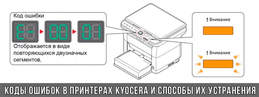
Коды ошибок принтеров и МФУ Kyocera, которые можно исправить самостоятельно
|
Код ошибки |
Значение ошибки |
Решение проблемы |
|
E-0001 (E1) |
Поврежден чип картриджа либо установлен неоригинальный картридж. |
Замените установленный картридж оригинальной версией изделия. Если хотите сэкономить, тогда купите и установите новый чип на картридж или перепрошейте принтер Kyocera. Однако предварительно не помешает попробовать сбросить ошибку соответствующей комбинацией клавиш (как это сделать, читайте в статье «Сброс ошибки установки неоригинального картриджа в принтерах Kyocera»). |
|
E-0002 (E2) |
Регион использования картриджа и принтера не совпадают. |
Замените чип или прошейте принтер Kyocera. |
|
E-0003 (E3) |
Заполнена память принтера или МФУ Kyocera. |
Отпечатайте ранее отсканированные листы или очистите очередь печати нажатием кнопки Стоп/Сброс (ранее отсканированные листы также удалятся из памяти принтера, даже если они еще не были распечатаны). |
|
E-0007 (E7) |
Тонер-картридж Kyocera израсходовал ресурс красящего вещества. |
Замените или заправьте картридж Kyocera (если используете совместимый или перезаправленный расходник, то после установки его в принтер не забудьте сбросить ошибку зажатием на 3-5 секунды кнопок [Ок] и [Сброс/Стоп]). |
|
E-0008 (E8) |
Открыта крышка принтера либо не работает датчик закрытия крышек устройства. |
Откройте и еще раз закройте переднюю и заднюю крышку принтера. Во время закрытия Вы должны услышать характерный щелчок. Если не помогло, то причина в неисправности датчика. |
|
E-0009 (E9) |
Лоток приема бумаги полон. |
Уберите все отпечатанные листы бумаги из выходящего лотка. Чтобы возобновить печать, нажмите кнопку [Старт]. |
|
E-0012 (E12) |
Ошибка памяти принтера Kyocera. |
Попробуйте уменьшить разрешение печати. Скорее всего, формат создаваемого отпечатка не соответствует возможностям принтера. |
|
E-0014 (E14) |
Установлен неверный формат бумаги (неподдерживаемый принтером Kyocera). |
Поменяйте бумагу на поддерживаемую принтером либо смените ее формат в настройках печати. Попробуйте обновить программное обеспечение. Возможно, это расширит поддерживаемые принтером Kyocera форматы. |
|
E-0015 (E15) |
Устройство не подключено к электрической сети либо на компьютере нет (не работает) драйвера принтера Kyocera. |
Проверьте подключение печатающего аппарата к электрической сети, а также целостность кабеля. Если ошибка не исчезает, скачайте драйвер принтера Kyocera и установите его на компьютер. |
|
E-0017 (E17) |
Ошибка передачи данных. |
Проверьте подключение принтера к компьютеру. Кабель не должен быть длиннее 5 метров, а также обязан поддерживать стандарт USB 2.0. Кроме того, переустановите драйвер принтера и утилиту Kyocera Client Tool. |
|
E-0018 (E18) |
Очередь печати заполнена. |
Очистите очередь печати нажатием кнопки [Сброс] либо через драйвер принтера. |
|
E-0019 (E19) |
Неверный формат печати. |
Отмените печать нажатием кнопки [Стоп/Сброс]. Выберите в настройках принтера соответствующий режим печати, а также установите в лоток поддерживаемый принтером формат бумаги. |
|
J-0000 (jam0000) |
Замятие бумаги за задней крышкой. |
Откройте крышку и извлеките бумагу. Проверьте надежность крепления бумаги в лотке, а также принтер на наличие посторонних предметов. Еще причина может быть в пружине выходного флажка. Если она растянулась, то может плохо работать фиксатор. Также проблема может быть из-за печки, сделайте ее ревизию, переборку и смазку. |
|
J-0501 (jam0501) |
Бумага застряла в принтере Kyocera |
Извлеките замятую бумагу. Проверьте надежность установки бумаги во входной лоток. Проверьте целостность роликов протяжки бумаги, а также принтер на наличие посторонних предметов. Если не помогло, стоит внимательно осмотреть ребра на направляющей пластине. На них могут образоваться сколы, трещины и заусенцы. Их можно слегка подчистить наждачной бумагой (нулевкой). |
|
J-0511 (jam0511) |
Принтер Kyocera замял бумагу. |
Извлеките замятую бумагу и повторите печать. Если проблема не исчезла, несите принтер в сервис. Скорее всего, изношен ролик протяжки бумаги. |
|
C7990 |
Бункер драм-картриджа (блока фотобарабана) заполнен отработанным тонером либо неисправен счетчик отработки красящего вещества. Еще проблема может быть в главной плате PWB. |
Осуществите чистку драм-картриджа (блока фотобарабана). Если проблема в датчике или плате, то нужно отнести принтер в СЦ на диагностику. |
|
F248 |
Ошибка обработки отпечатываемого материала. |
Перезагрузите принтер. Уберите неподдерживаемые спецсимволы из отпечатка. Обновите ПО принтера Kyocera. Смените режим работы принтера с PDL на GDI (Пуск -> Принтеры -> Свойства -> Параметры устройства). |
|
PF |
Отсутствует бумага в лотке подачи. |
Загрузите листы бумаги во входной лоток. Если принтер по-прежнему не печатает, значит нужно искать проблему в чем-то другом. |
|
1101 |
Ошибка сканирования через сеть из-за неправильного имени SMTP сервера. |
Пропишите DNS-адреса помимо прочих настроек печати по сети. |
|
1102 |
Некорректная настройка сканера для работы через сеть |
Зайдите в Web-панель управления принтером (нужно в адресную строку браузера ввести iP принтера Kyocera). Далее в зависимости от модели введите логин и пароль (Admin/Admin или просто admin00 без логина). Далее следуйте инструкции:
Логин и пароль нужны обязательно, если их нет, то следует создать. |
|
2101 |
Ошибка передачи данных при сканировании через сеть. |
Правильно настройте параметры (как для ошибки 1102), только предварительно отключите на ПК антивирус и брандмауэр. |
Если Вы испытали все способы, но не смогли убрать ошибку, то следует нести печатающее устройство в сервисный центр. Кроме того, есть ряд ошибок (высвечиваемых на дисплее принтера), которые нельзя устранить в домашних условиях. Соответствующие коды ошибок принтеров Kyocera представляем в очередной таблице.
Коды ошибок принтеров и МФУ Kyocera, которые нужно устранять в сервисном центре
|
Код ошибки |
Значение ошибки |
Решение проблемы |
|
0030 |
Неисправность платы управления факсом принтера. |
Замена платы. |
|
0100 |
Неисправность платы управления или флеш-памяти принтера. |
Замена платы. |
|
0120 |
Ошибка чтения mac-адреса из-за неисправности флеш-памяти принтера. |
Замена платы. |
|
0190 |
Неисправность платы управления или флеш-памяти принтера. |
Замена платы. |
|
0630 |
Неисправность платы управления принтера. |
Замена платы. |
|
1020 |
Неисправность мотора, привода или отсутствие контакта. |
Разборка принтера и замена изношенных частей. Проверка надежности подключений, замена разорванных (прогоревших) кабелей. Ремонт или замена привода мотора. |
|
1040 |
Неисправность мотора, привода или отсутствие контакта. |
Разборка принтера и замена изношенных частей. Проверка надежности подключений, замена разорванных (прогоревших) кабелей. Ремонт или замена привода мотора. |
|
2000 |
Неисправность главной платы управления, соединительного кабеля или привода принтера. |
Проверить ремни, шестерни и ролики привода. Смазать или заменить, если есть дефекты. Заменить привод или главную плату. |
|
3100 (C3100) |
Неисправность главной платы, привода сканера, датчика положения или нарушение целостности соединений. |
Проверить наличие разрывов и отсутствия контакта. Смазать или заменить изношенные элементы привода. Заменить привод, главную плату, датчик или соединительный кабель. Если Вам повезло, то возможно забыли отключить фиксатор блока сканера. |
|
3101 |
Сетевой кабель не подсоединен, или нарушена работа концентратора. Еще может быть из-за наличия вирусов в системе или неправильно заданным параметрам сервера SMTP. |
Проверить соединения, правильно настроить параметры сети. |
|
3300 |
Неисправность главной платы, датчика CIS или соединительного кабеля. |
Проверить контакты, заменить плату или датчик. |
|
3500 |
Неисправность главной платы или нарушение соединения контактов. |
Проверить контакты, заменить плату. |
|
4000 (C4000) |
Неисправность главной платы, привода сканера или нарушение соединений. Однако чаще всего ошибка лазера. |
Проверить контакты, заменить плату или привод блока сканера. Почистить лазер, смазать ось полигон-мотора, либо полностью заменить блок лазера. |
|
4200 |
Неисправность главной платы, блока сканера или датчика BD. |
Отключить питание принтера на 30 минут. Если не помогло, то следует заменить привод сканера или главную плату принтера. |
|
6000 (С6000) |
Неисправность главной платы, термостата, печки или нарушение соединения контактов. |
Проверить и поправить контакты. Заменить фьюзер. Ремонт или замена печки, термодатчика, термопредохранителя и т.д. |
|
6020 |
Сгорание термистора или главной платы. |
Замена термистора или главной платы. |
|
6030 |
Неисправность главной платы, термостата или термистора. Возможно, причина в отсутствии контакта. |
Проверить соединения. Заменить плату, термостат или термистор. |
|
6400 |
Неисправность главной платы, отсутствие питания или контакта. |
Заменить плату или источник питания. |
|
F000 |
Неисправность главной платы или отсутствие контакта. |
Проверить соединение ремня безопасности. Заменить ремень или плату управления. |
|
F020 |
Неисправность элементов памяти принтера. |
Перезагрузить принтер. Если ошибка не устранилась – заменить плату управления. |
|
F040 |
Неисправность главной платы принтера. |
Перезагрузить принтер. Если ошибка не устранилась – заменить плату управления. |
|
F05D |
Неисправность главной платы. Сбой программного оборудования привода. Проблемы с прошивкой принтера Kyocera. |
Перезагрузить принтер. Если ошибка не устранилась – заменить плату управления. Перепрошить принтер Kyocera. |
|
F245 F246 F247 F375 |
Принтер Kyocera заблокирован из-за проблемы, вызванной отказом источника питания. |
Нужно перепрошить принтер специальной сервисной микропрограммой. |
Обратите внимание: Если у печатающего устройства нет дисплея, то определить проблему можно по светодиодным индикаторам, встроенным в панель управления принтером. Например, у Kyocera Ecosys P2135D нужно сосчитать количество миганий индикаторов красного цвета и таким образом определить число, указывающее на ту или иную ошибку. В свою очередь, у модели Kyocera FS-1040 все зависит от темпа мигания светодиода с надписью «Внимание!» («Attention!»):
- Мигает медленно – указывает на отсутствие бумаги в лотке или тонера в картридже.
- Мигает быстро – оповещает о проблеме с памятью устройства, переполненном лотке или замятии бумаги, а также об использовании неоригинальных расходных материалов.
- Горит постоянно – говорит о проблемах с картриджем или фотобарабаном либо указывает на открытые крышки принтера.
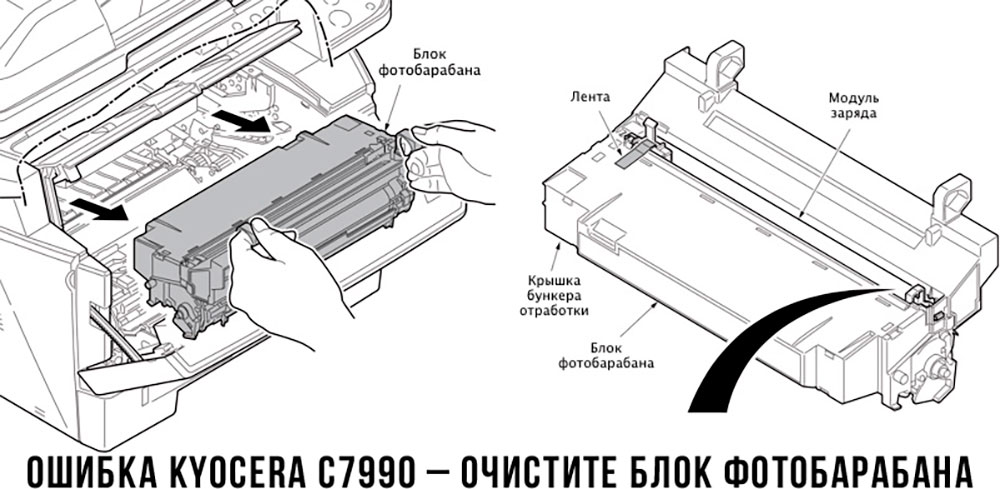
Чтобы потребитель мог наверняка определить проблему, рекомендуем использовать утилиту Kyocera Client Tool, которая идет в комплекте с драйверами принтера.
Ваше Имя:
Ваш вопрос:
Внимание: HTML не поддерживается! Используйте обычный текст.
Оценка:
Плохо
Хорошо
Введите код, указанный на картинке:


 Если с аппаратом Kyocera TASKalfa 1800, Kyocera TASKalfa 2200 произошла проблема, откроется следующий экран с уведомлением.
• Индикатор [Внимание] на панели управления горит или мигает.
• На дисплее сообщений панели управления аппарата появилось сообщение об ошибке.
Если индикатор [Внимание] горит или мигает и на дисплее сообщений панели управления аппарата появилось сообщение об ошибке, проверьте KYOCERA Client Tool или Монитор состояния.
ПРИМЕЧАНИЕ Если индикаторы постоянно горят и мигают не так, как описано выше, вероятно, произошла ошибка службы. Выключите питание, отсоедините шнур питания и вставьте его обратно, после чего включите питание. Это может помочь сбросить ошибку. Если ошибка не исчезает, свяжитесь со своим представителем сервисной службы (тел. в Минске +375 17 291-28-24)
Ниже описаны неполадки, которые не могут быть устранены пользователем
|
Дисплей сообщений |
Описание |
Меры устранения |
|
Бункер отраб тонера перепол. или не уст. |
Бункер для отработанного тонера установлен неправильно |
Установите Бункер для отработанного тонера должным образом |
|
Бункер для отработанного тонера заполнен |
Замените бункер отработанного тонера |
|
|
Встряхните картр. с тонером |
Тонер слежался |
Откройте переднюю крышку аппарата и вытяните контейнер с тонером. Сильно встряхните контейнер с тонером и установите его на место |
|
Вызовите сервисный персонал. |
В аппарате произошла ошибка |
Обратите внимание на код ошибки, отображаемый в дисплее сообщений, и свяжитесь с представителем сервисной службы (тел. в Минске +375 17 291-28-24) |
|
Выньте бумагу с внутреннего лотка |
Извлеките бумагу из внутреннего лотка. Нажмите клавишу [OK], чтобы возобновить печать |
|
|
Добавьте тонер |
Закончился тонер |
Замените контейнер с тонером TK-4105 |
|
Загрузите бумагу в кассету # |
↑↓ (отображается попеременно) |
Загрузите бумагу. Нажмите клавишу [OK] и перейдите к следующему шагу. • Для выбора другого устройства подачи выберите [Выберите бумагу]. • Для печати на бумаге, в настоящее время находящейся в устройстве подачи, выберите [Продолж. без изм.] |
|
Загрузите бумагу в универсальный лоток |
↑↓ (отображается попеременно) |
Загрузите бумагу. Нажмите клавишу [OK] и перейдите к следующему шагу. • Для выбора другого устройства подачи выберите [Выберите бумагу]. • Для печати на бумаге, в настоящее время находящейся в устройстве подачи, выберите [Продолж. без изм.] |
|
Закройте автоподатчик оригиналов |
Открыт автоподатчик оригиналов |
Откройте и закройте автоподатчик оригиналов |
|
Закройте крышку автопод. оригиналов |
Открыта верхняя крышка автоподатчика оригиналов |
Откройте и закройте крышку автоподатчика оригинало |
|
Закройте переднюю крышку |
Открыта передняя крышка |
Откройте и закройте переднюю крышку |
|
Закройте правую крышку # |
Открыта какая-либо крышка |
Откройте и закройте крышку, обозначенную на экране |
|
Замятие бумаги. (DP) |
В автоподатчике произошло замятие бумаги. |
См. Устранение замятия бумаги в Руководстве по эксплуатации и извлеките замятую бумагу |
|
Замените МК |
Необходимо производить замену деталей комплекта техобслуживания MK-4105 (ремкомплекта) каждые 150 000 страниц печати. |
Данная операция должна производиться специалистом. Обратитесь к представителю сервисной службы (тел. в Минске +375 17 291-28-24) |
|
Замятие |
Произошло замятие бумаги в кассете или универсальном лотке |
См. Устранение замятия бумаги и извлеките замятую бумагу |
|
Извлеките оригиналы из автоподатчика |
Для продолжения работы необходимо извлечь оригиналы из автоподатчика оригиналов |
Извлеките оригиналы из автоподатчика оригиналов |
|
Кабель USB был отключен |
Кабель USB не подключен |
Нажмите клавишу [OK] и подключите кабель USB |
|
ПК выключен |
Нажмите клавишу [OK] и включите ПК |
|
|
Не удается найти KYOCERA Client Tool |
Нажмите клавишу [OK] и откройте KYOCERA Client Tool на ПК |
|
|
Макс. к-во сканируемых страниц |
Превышен предел сканирования |
Дальнейшее сканирование невозможно. Задание отменено. Нажмите клавишу [OK] |
|
Мало тонера. (Зам., когда законч.) |
Скоро понадобится заменить контейнер с тонером |
Получите новый контейнер с тонером TK-4105. |
|
Не оригинальный тонер |
Установлен контейнер с тонером не марки Kyocera |
Производитель не несет ответственности за повреждения, вызванные использованием неоригинального тонера. Мы рекомендуем использовать исключительно оригинальные контейнеры с тонером TK-4105. . |
|
Неверный ид. уч. зап. Задание отменено |
Указан неверный идентификатор учетной записи при внешней обработке задания. Задание отменено |
Нажмите клавишу [OK] |
|
Невозможна двусторонняя печать на этой бумаге |
Не возможна печать на бумаге выбранного формата или типа |
Нажмите клавишу [OK] и перейдите к следующему шагу: |
|
Недостаточно памяти. Невозможно начать выполнение задания |
Невозможно начать выполнение задания |
Повторите попытку позже |
|
Ограничено алгоритмом учета заданий(Печать) |
Задание отменено, поскольку его выполнение ограничено функцией учета заданий |
Нажмите клавишу [OK] |
|
Ограничено алгоритмом учета заданий(Сканер) |
Задание отменено, поскольку его выполнение ограничено функцией учета заданий |
Нажмите клавишу [OK] |
|
Очистите сканер |
Произошло загрязнение сканера |
Очистите щелевое стекло с помощью чистящей салфетки, поставляемой вместе с автоподатчиком оригиналов. |
|
Ошибка. Выключить |
— |
Отключите и снова включите аппарат с помощью выключателя питания |
|
Память переполнена |
Невозможно продолжить выполнение задания из-за отсутствия свободной памяти |
Измените разрешение печати с Быстр1200 до 600 dpi. См. Printer Driver User Guide |
|
Память сканера переполнена |
Дальнейшее сканирование невозможно из-за нехватки памяти сканера. |
Для отмены задания нажмите [OK] |
|
Перезагрузка печати. Задание отменено |
Предупреждение. Недостаточно памяти принтера. Задание отменено |
Нажмите клавишу [OK] |
|
Превышено ограничение учета заданий |
Превышено число распечаток из-за ограничения алгоритмом учета заданий. Достигнут предел печати |
Это задание отменено. Нажмите клавишу [OK] |
|
Уст.другую кассету |
Выбрано «Сдвиг» |
Для использования сдвига необходимо загрузить в другой лоток бумагу такого же формата, что и в выбранном устройстве подачи, но в другой ориентации |
|
Установите все оригиналы обратно и нажмите клавишу [Старт]. |
Возникает при печати двусторонних документов в режиме ручной двусторонней печати |
Извлеките оригиналы из автоподатчика оригиналов, расположите их в первоначальном порядке и положите обратно. Нажмите клавишу [OK], чтобы возобновить печать. Для отмены задания нажмите [Стоп] |
|
Установлен неизвестный тонер. ПК |
Региональная спецификация контейнера с тонером не соответствует спецификации аппарата |
Установите оригинальный контейнер с тонером Замените контейнер с тонером TK-4105 |
Если при работе с копировальном аппаратом у вас возникли проблемы, и система выдает код ошибки, вы можете идентифицировать ее с помощью данной таблицы.
Коды ошибок Kyocera-Mita указаны для более поздних моделей копиров. Если вы являетесь владельцем более ранней модели, необходимо к трехзначному коду ошибки прибавить знак «0».
Общие ошибки
| Код ошибки | Описание |
|---|---|
| 0030 | Fax control PWB system problem |
| 0070 | Fax control PWB incompatibility detection problem |
| 0100 | Backup memory read/write problem (main board) |
| 0110 | Backup memory data problem (main board) |
| 0120 | Drum EEPROM read/write problem (для 2550) |
| 0130 | Backup memory read/write problem (main PCB EEPROM) (для 1650/2050/2550) |
| 0140 | Backup memory data problem (main PCB EEPROM) (для 1650/2050/2550) |
| 0150 | Backup memory read/write problem (engine board) |
| 0160 | Backup memory data problem (engine board) |
| 0170 | Accounting count problem |
| 0180 | Machine number mismatch |
| 0210 | Communication problem between the main board and engine board (для KM-1500/1620/2020/1635/2035/1650/2050/2550/6030/8030, FS-1018/1118) |
| Communication problem between the main board and operation board (для KM-1525/1530/2030/2530/3530/6230/4530/5530/6330/7530) | |
| 0240 | Printer board PWB communication problem |
| 0250 | Scanner network board communication problem |
| 0280 | Communication problem between the fax control PWB and main PWB |
| 0320 | Side deck communication problem |
| 0340 | Finisher communication problem |
| 0410 | Optional DP communication problem |
| 0420 | Optional first paper feeder communication problem |
| Large paper deck /paper feed desk communication problem /Side deck communication problem | |
| 0440 | Finisher communication problem |
| 0450 | Mailbox communication problem |
| 0470 | Switchback unit communication problem |
| 0500 | Optional second paper feeder communication problem |
| 0510 | Optional third paper feeder communication problem |
| 0600 | DIMM problem (для 2530/3530) |
| 0610 | Bitmap (DIMM) problem |
| 0620 | Memory input interface problem |
| 0630 | DMA problem |
| 0640 | Hard disk drive problem |
| 0800 | Image processing problem (JAM05 is detected twice) |
| 0820 | Fax control PCB CG ROM checksum error |
| 0830 | Flash ROM program area checksum error |
| 0860 | Fax control PCB software switch checksum error |
| 0870 | Fax control PWB to main PWB high capacity data transfer problem |
| 0880 | Fax control PWB program archive problem |
| 0890 | Fax control PCB CG font archive problem |
| 0900 | Fax software incompatibility detection problem |
| 0920 | Fax file system error |
| 0960 | Developer EEPROM read/write problem (для 2550/6030/8030) |
| 1000 | Exposure lamp problem |
| 1010 | Lift motor 1 error |
| 1020 | Lift motor 2 error |
| 1030 | Lift motor 3 error |
| 1040 | Lift motor 4 error |
| 1100 | Paper deck motor 1 problem [Drawer 3] |
| 1110 | Paper deck motor 2 problem [Drawer 4] |
| 1120 | Deck right lift position problem |
| 1130 | Deck left lift position problem |
| 1140 | Side deck lift motor (going up) problem |
| 1150 | Side deck lift motor (going down) problem |
| 1160 | Large paper deck (paper feed desk) sequence problem |
| 1170 | Large paper deck (paper feed desk) incorrect type problem |
| 2000 | Main motor problem |
| Image forming motor problem (для 6230/4530/5530/6330/7530) | |
| 2500 | Paper feed motor problem |
| 2550 | Paper conveying motor problem (для 4530/5530) |
| 2600 | Deck conveying motor /desk drive motor problem |
| 2640 | Side deck drive motor problem |
| 3100 | Scanner carriage problem |
| 3200 | Exposure lamp problem |
| 3300 | Optical system (AGC) problem |
| 4000 | Polygon motor synchronization problem |
| 4010 | Polygon motor steady-state problem |
| 4100 | BD initialization (A) problem |
| 4110 | BD initialization (B) problem |
| 4200 | BD steady-state problem |
| 5100 | Main charger problem |
| 5110 | Transfer/separation high voltage problem |
| 5300 | Broken cleaning lamp wire |
| 5500 | Drum surface potential sensor problem 1 |
| 5510 | Drum surface potential sensor problem 2 |
| 5600 | Drum surface potential problem 1 |
| 5610 | Drum surface potential problem 2 |
| 6000 | Broken fixing heater wire |
| 6020 | Abnormally high fixing unit thermistor temperature |
| 6030 | Broken fixing unit thermistor |
| 6050 | Abnormally low fixing unit thermistor temperature |
| 6100 | Broken fixing heater wire |
| 6200 | Abnormally low fixing unit thermistor temperature |
| 6300 | Abnormally high fixing unit thermistor temperature |
| 6400 | Zero-crossing signal problem |
| 6410 | Fixing unit connector insertion problem |
| 6420 | Fixing fuse cut problem |
| 6420 | Broken fixing unit thermistor wire |
| 7100 | Toner sensor problem |
| 7300 | Broken external temperature thermistor wire (для KM-1505/1510/1810/4230/5230/6230) |
| Toner sensor problem/ Toner hopper problem (для KM-2530/3530/3035/4035/5035/6230/4530/5530/6330/7530/6030/8030) | |
| 7310 | Short-circuited external temperature thermistor |
| 7400 | Image formation unit connector insertion problem |
| Developing unit connector insertion problem (для 2550) | |
| 7410 | Drum unit connector insertion problem |
| 7750 | Drum type mismatch problem A (для 1635/2035) |
| 7760 | Drum type mismatch problem B (для 1635/2035) |
| 7800 | Broken external temperature thermistor |
| 7810 | Short-circuited external temperature thermistor |
KM-1500, FS-1018/1118 (KM-1820)
| Код ошибки | Описание |
|---|---|
| 0220 | Communication problem between the main board and operation board (для 1018/1118) |
| F— | Controller system error (для 1018/1118) |
| F010 | ROM checksum error (для 1118) |
| F012 | |
| 7980 | Waste toner reservoir overflow problem (when the total number of copies is less than 100 thousand sheets) |
| 7990 | Waste toner reservoir overflow problem (when the total number of copies is 100 thousand sheets or more) |
KM-1505/1510/1810/1525/1530/2030
| Код ошибки | Описание |
|---|---|
| 0210 | Printer board communication problem (для 1505/1510/1810) |
| 0400 | DIMM problem |
| 0410 | Bitmap problem |
| 0430 | DMA problem |
| 1040 | Optical system problem (AGC) |
Kyocera-Mita 3035/4035/5035
| Код ошибки | Описание |
|---|---|
| 0100 | Operation unit PCB backup memory read/write error |
| 0110 | Operation unit PCB backup memory data problem |
| 0210 | MMI communication problem |
| 0320 | Energy save communication problem |
| 7450 | Image formation unit fuse cut problem |
Kyocera Mita 4230/5230
| Код ошибки | Описание |
|---|---|
| 0010 | Memory copy PCB 1 communication problem |
| 0030 | Memory copy PCB 2 communication problem |
| 0100 | RAM/ROM problem |
| 0220 | Communication problem between the engine PCB and main PCB |
| 0230 | Scanner communication problem |
| 0260 | Memory copy PCB 1 communication problem |
| 0320 | Large paper deck communication problem /Paper feed desk communication problem |
| 0360 | Memory copy PCB 2 communication problem |
| 0370 | Communication microcomputer problem |
| 1040 | Optical system problem (AGC) |
| 2100 | Paper conveying motor problem |
| 2200 | Side registration motor problem |
| 2300 | Paper feed motor problem |
| 2310 | Desk drive motor problem |
| 2410 | Upper lift motor problem |
| 2420 | Lower lift motor problem |
| 2430 | Upper desk lift motor problem |
| 2440 | Lower desk lift motor problem |
| 3320 | Scanner watchdog problem |
| 3400 | Original detection position problem |
| 7400 | Toner hopper problem |
| 9200 | Deck paper conveying motor problem |
| 9210 | Paper deck motor 1 problem |
| 9220 | Paper deck motor 2 problem |
| 9230 | Right lift position problem |
| 9240 | Left lift position problem |
Kyocera-Mita 6030/8030
| Код ошибки | Описание |
|---|---|
| 0060 | Main PWB type mismatch error |
| 0130 | Backup memory (EEPROM) device problem |
| 0140 | Backup memory (EEPROM) data problem |
| 0220 | Scanner communication problem |
| 0330 | Relay board communication problem |
| 0460 | Duplex unit communication problem |
| 0470 | Sheet inserter communication problem (optional document finisher) |
| 0500 | Paper feed unit communication error (cassette 1 and 2) |
| 0510 | Paper feed unit communication error (cassette 3 and 4) |
| 0700 | Side feeder EEPROM error (optional side feeder) |
| 0750 | Document finisher EEPROM error |
| 0970 | Cleaning unit EEPROM error |
| 1200 | Duplex side registration motor error |
| 2100 | Developing motor error |
| 2200 | Drive motor error |
| 2300 | Fuser motor error |
| 2550 | Transfer motor error |
| 3210 | CIS lamp problem |
| 3310 | Optical system (AGC) problem (DP) |
| 3500 | Communication error between scanner and SHD |
| 3900 | Backup memory read/write error (scanner PWB) |
| 3910 | |
| 4120 | BD initialization (C) problem |
| 7200 | Broken drum thermistor wire |
| 7210 | Shorted drum thermistor |
| 9040 | DP lift motor going up error |
| 9050 | DP lift motor going down error |
| 9060 | DP EEPROM error |
| 9070 | Communication problem between DP and SHD |
| 9080 | Communication problem between DP and CIS |
Kyocera Mita 6230
| Код ошибки | Описание |
|---|---|
| 0010 | Memory PCB communication problem |
| 0100 | RAM/ROM problem |
| 0260 | Memory copy PCB 1 communication problem |
| 0350 | Mailbox communication problem |
| 0370 | Communication microcomputer problem |
| 0380 | Hard disk problem |
| 0390 | DIMM problem |
| 1040 | Optical system problem (AGC) |
| 2100 | Drive motor problem / Paper conveying motor problem |
| 2200 | Paper feed motor problem |
| 2300 | Large paper deck right lift motor problem |
| 2310 | Large paper deck left lift motor problem |
| 2420 | Upper lift motor problem |
| 2430 | Lower lift motor problem |
| 6500 | Broken fixing unit thermistor wire |
| 7200 | Broken drum thermistor wire |
| 7210 | Shorted drum thermistor |
| 7220 | Broken drum heater wire |
KyoceraMita 6330/7530
| Код ошибки | Описание |
|---|---|
| 1060 | Large paper deck left lift motor problem |
| 2550 | Drive motor problem |
| 7520 | Shorted drum thermistor |
| 7530 | Broken drum thermistor wire |
Ошибки финишеров
| Код ошибки | Описание |
|---|---|
| 8010 | Finisher paper conveying motor problem |
| 8030 | Finisher (upper) paper conveying belt problem |
| 8140 | Finisher tray elevation motor problem /Main tray problem |
| 8170 | Finisher front side registration motor problem |
| 8180 | Finisher rear side registration motor problem |
| Finisher rear jogger motor problem (для 4230/5230) | |
| 8190 | Finisher trailing edge registration motor problem |
| 8210 | Finisher stapler motor problem |
| 8220 | Finisher rear stapler problem |
| 8300 | Document finisher centerfold unit communication problem |
| 8310 | Document finisher centerfold unit side registration guide problem |
| 8320 | Document finisher centerfold unit centering plate problem |
| 8330 | Document finisher centerfold blade problem |
Ошибки финишеров KM-2530/3530/3035/4035/5035
| Код ошибки | Описание |
|---|---|
| 8300 | Booklet stitcher paper ejection motor problem |
| 8310 | Booklet stitcher elevation motor problem |
| 8320 | Booklet stitcher rear jog motor problem |
| 8330 | Booklet stitcher front jog motor problem |
| 8340 | Booklet stitcher staple motor problem |
| 8350 | Booklet stitcher batch processing motor problem |
| 8360 | Booklet stitcher stapler shift motor problem |
| 8370 | Booklet stitcher paddle motor problem |
| 8380 | Booklet stitcher folding problem |
| 8390 | Booklet stitcher backup RAM data problem |
| 8400 | Booklet stitcher incorrect type problem |
| 8410 | Booklet stitcher punch motor problem |
| 8420 | Booklet stitcher shift motor problem |
| 8430 | Booklet stitcher punch communication problem |
| 8440 | Booklet stitcher punch sensor problem |
| 8450 | Booklet stitcher side punch sensor problem |
| 8460 | Booklet stitcher punch backup RAM data problem |
| 8470 | Booklet stitcher punch dust sensor problem |
| 8480 | Booklet stitcher broken punch power source wire problem |
| 8500 | Mailbox drive motor problem |
Ошибки финишера KM-6230
| Код ошибки | Описание |
|---|---|
| 8180 | Finisher rear jogger motor problem |
| 8310 | Booklet stitcher paper ejection motor problem |
| 8320 | Booklet stitcher elevation motor problem |
| 8330 | Booklet stitcher jog motor problem |
| 8340 | Booklet stitcher staple motor problem |
| 8350 | Booklet stitcher stapler unit shift motor problem |
| 8360 | Booklet stitcher stack level detection sensor problem |
| 8370 | Booklet stitcher punch motor problem |
| 8380 | Booklet stitcher punch shift motor problem |
| 8390 | Booklet stitcher swing motor problem |
| 8400 | Booklet stitcher backup RAM data problem |
| 8410 | Booklet stitcher punch unit backup RAM data problem |
| 8420 | Booklet stitcher positioning plate motor problem |
| 8430 | Booklet stitcher folding motor problem |
| 8440 | Booklet stitcher guide motor problem |
| 8450 | Booklet stitcher jog motor problem |
| 8460 | Booklet stitcher rear staple motor problem |
| 8470 | Booklet stitcher front staple motor problem |
| 8480 | Booklet stitcher thrust motor problem |
| 8490 | Booklet stitcher communication error |
Ошибки финишеров KM-6330/7530/6030/8030
| Код ошибки | Описание |
|---|---|
| 8000 | Document finisher incorrect type problem (для 6330/7530) |
| 8020 | Finisher punch motor problem |
| 8040 | Finisher lower paper conveying belt problem |
| 8150 | Finisher multi job tray problem |
| 8170 | Front upper side-registration guide problem |
| 8180 | Finisher rear upper side-registration guide problem |
| 8190 | Finisher lower side-registration guide problem |
| 8220 | Finisher front clincher problem |
| 8230 | Finisher rear stapler problem |
| 8240 | Finisher rear clincher problem |
Чем мы можем вам сегодня помочь?
Изменено: Чт, 12 Июл, 2018 at 3:35 PM
В машинах Kyocera P6021cdn, P6026cdn, M6026cdn/cidn, M6526cdn/cidn, FSC5150/5250/5350 и многих других довольно часто приходится сталкиваться с ошибкам C7401, C7402, C7403, C7404.
Описание этих ошибок в сервисной документации такое: «Developing unit non-installing error». Суть ошибок — машина не «видит» сигнала с датчика концентрации тонера в блоке проявки (7401 –Black, 7402 – Cyan, 7403 – Magenta, 7404 – Yellow).
Т.е. показания датчика выходят за допустимый диапазон, что может быть вызвано чрезмерно низкой концентрацией тонера в девелопере или недостаточным количеством девелопера в блоке проявки. Предлагаемый сервисной документацией способ устранения проблемы обычно заканчивается весьма дорогим пунктом — заменой блоков проявки целиком.
Частые причины появления проблемы – использование «не очень совместимого» тонера или использование машины не по своему назначению. Машины предназначены для офисной печати в нормальных условиях, и не очень хорошо справляются с печатью при высоком или низком заполнении тонером напечатанных страниц, а также в условиях высокой или низкой влажности воздуха.
Рекомендуемый нами метод лечения, опробованный на нескольких машинах:
- Для очистки совести проверить разъемы и провода на пути от датчиков концентрации тонера до платы.
- Проверить систему подачи тонера – часто ломаются шестерни шнеков подачи тонера, которые находятся в блоке ленты переноса.

- Опустить магнит в бункер отработки, чтобы выяснить имел ли место «вынос» девелопера в отработку.
- При отсутствии девелопера в бункере отработки вручную добавить и распределить тонер в блок проявки. Добавлять через входное отверстие блока проявки, распределять вращением валов блока проявки за шестерню. Обычно для вывода машины из состояния ошибки достаточно добавить 3-5 г тонера и вращать вручную шестерню блока проявки 2-3 минуты.


- При присутствии девелопера в бункере отработки сначала вручную добавить совместимый носитель в блок проявки, затем тонер. Добавлять через входное отверстие блока проявки, распределять вращением валов блока проявки за шестерню. Примерное количество носителя, которое нужно добавить, можно выяснить сравнением веса проблемного и «живого» блока проявки.
- После входа машины на готовность запустить из меню машины процедуру DEV-CLN (1 раз, чтобы не заклинить систему вывода отработки!) затем калибровку цвета. Это позволит машине довести концентрацию тонера до установленных значений.
Профилактика:
- Обновление прошивки. Kyocera иногда вносит в прошивки коррекции, связанные с алгоритмом подкачки тонера.
- Использование «нормального» тонера.
- Беседа с клиентом о том, что офисная машина предназначена для печати офисных документов, а не для оперативной полиграфии и т.п.
Была ли эта статья полезной?
Да
Нет
Отправить отзыв
К сожалению, мы не смогли помочь вам в разрешении проблемы. Ваш отзыв позволит нам улучшить эту статью.